I believe this is a post for a smaller group of (somewhat nerdy) people, so I will instead write it in English, rather then in Swedish towards the usual Swedish blog audience. Enjoy!
At the moment the restoration is paused due to hard drive failure.
Introduction
I got a Xbox (original) from 2003. This is the version 1.4, due to the Focus chip. [1, 2, 3]. In this time when the xbox was manufactured, the world of capacitors was out of balance. Something that later got the name Capacitor plague. So to extend the life span of an old tech relic, the old faulty capacitor(s) most be talken care of.
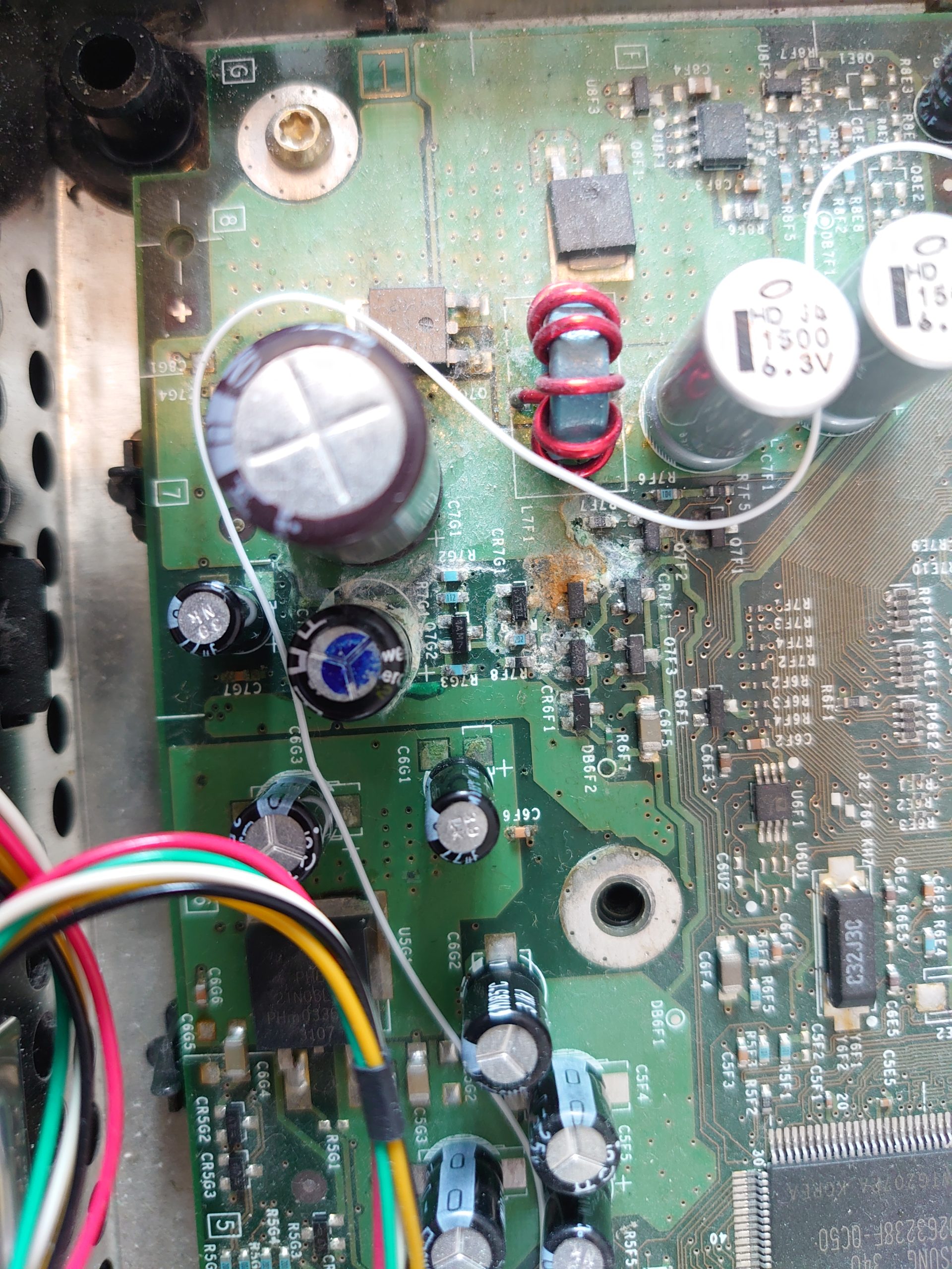
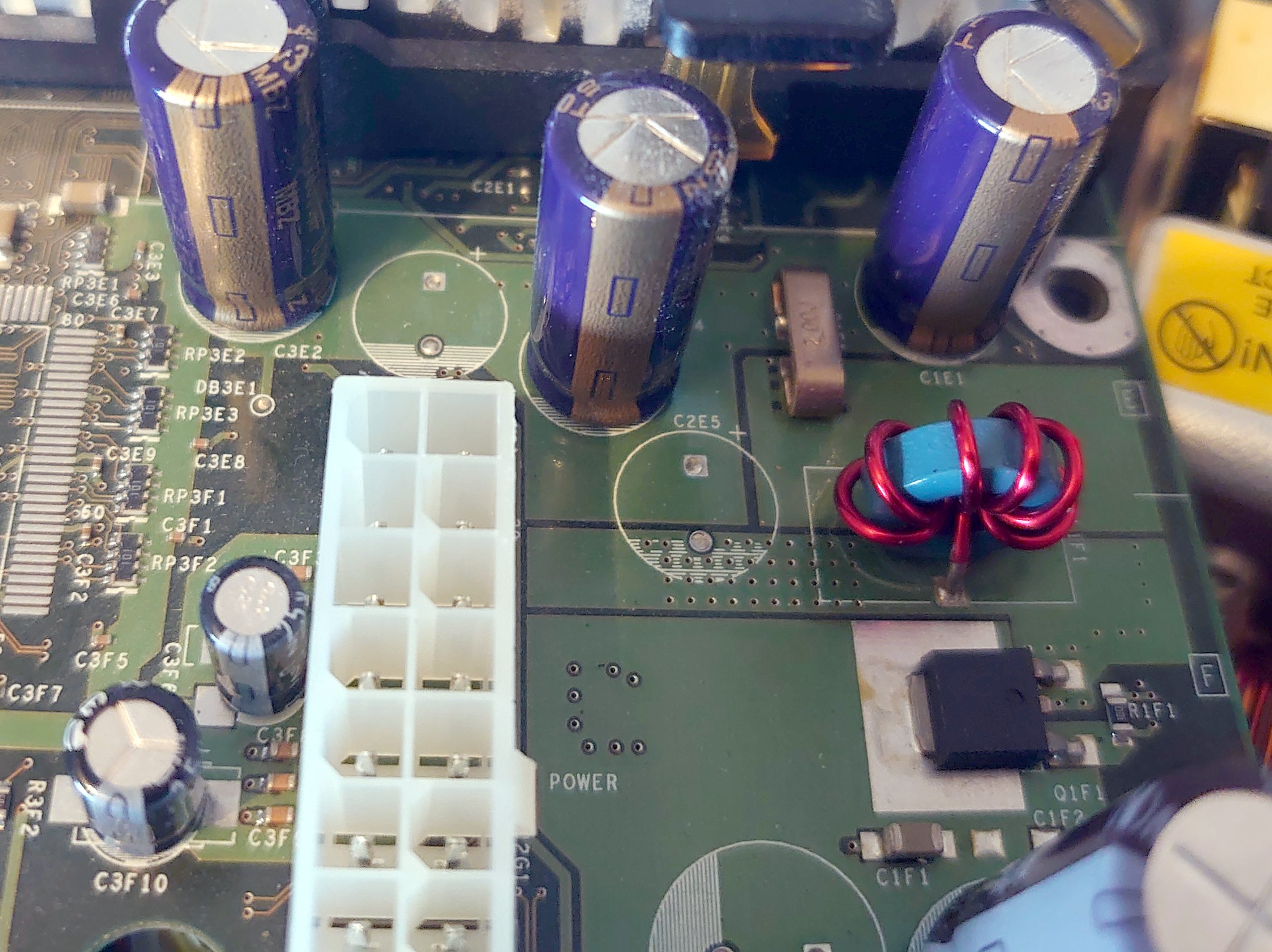
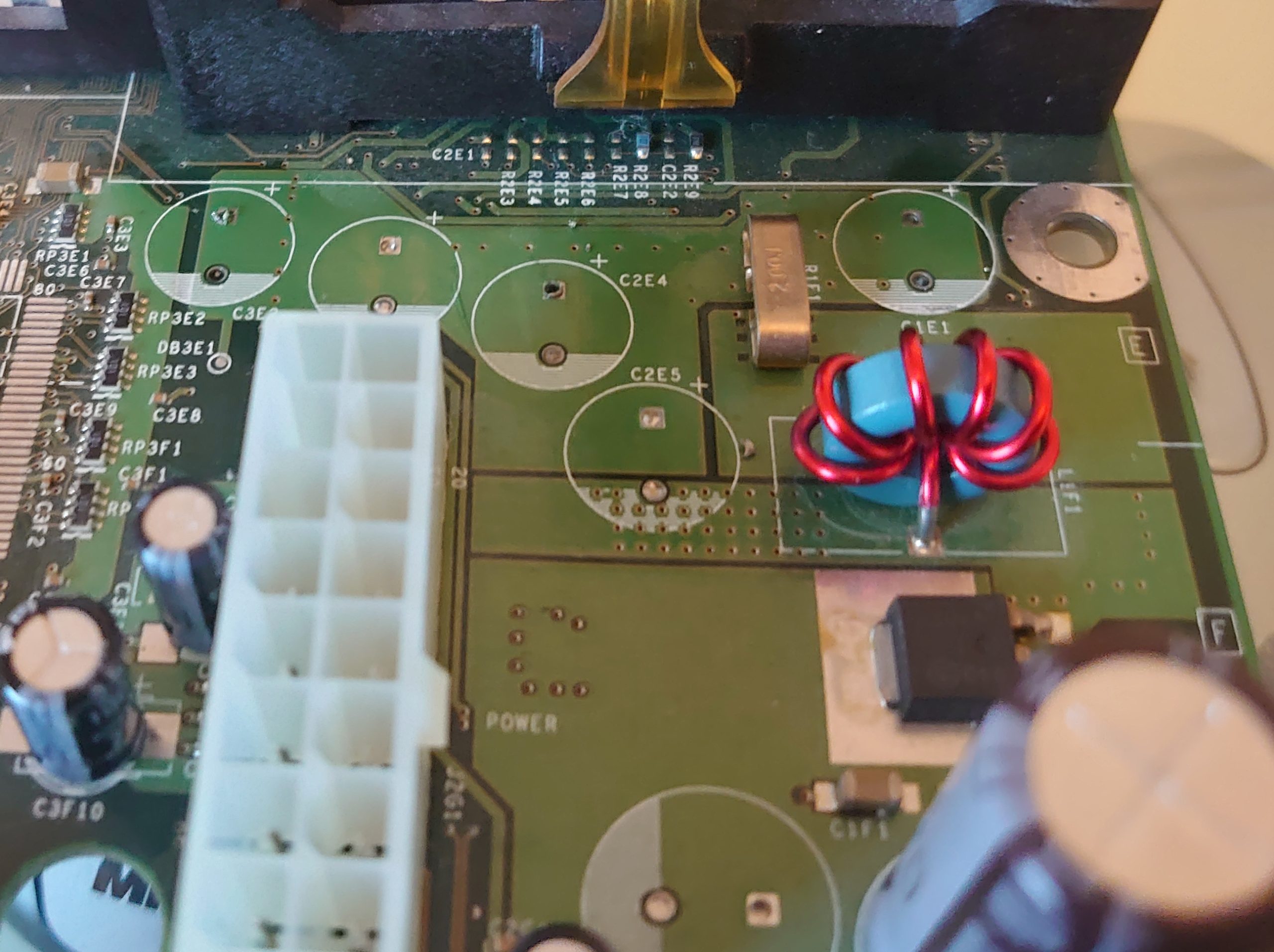
1.1 Removing the clock capacitor
Quick and dirty rescue missing – Locate the affected area, eliminate the bad capacitor, and afterwards clean & secure the area.
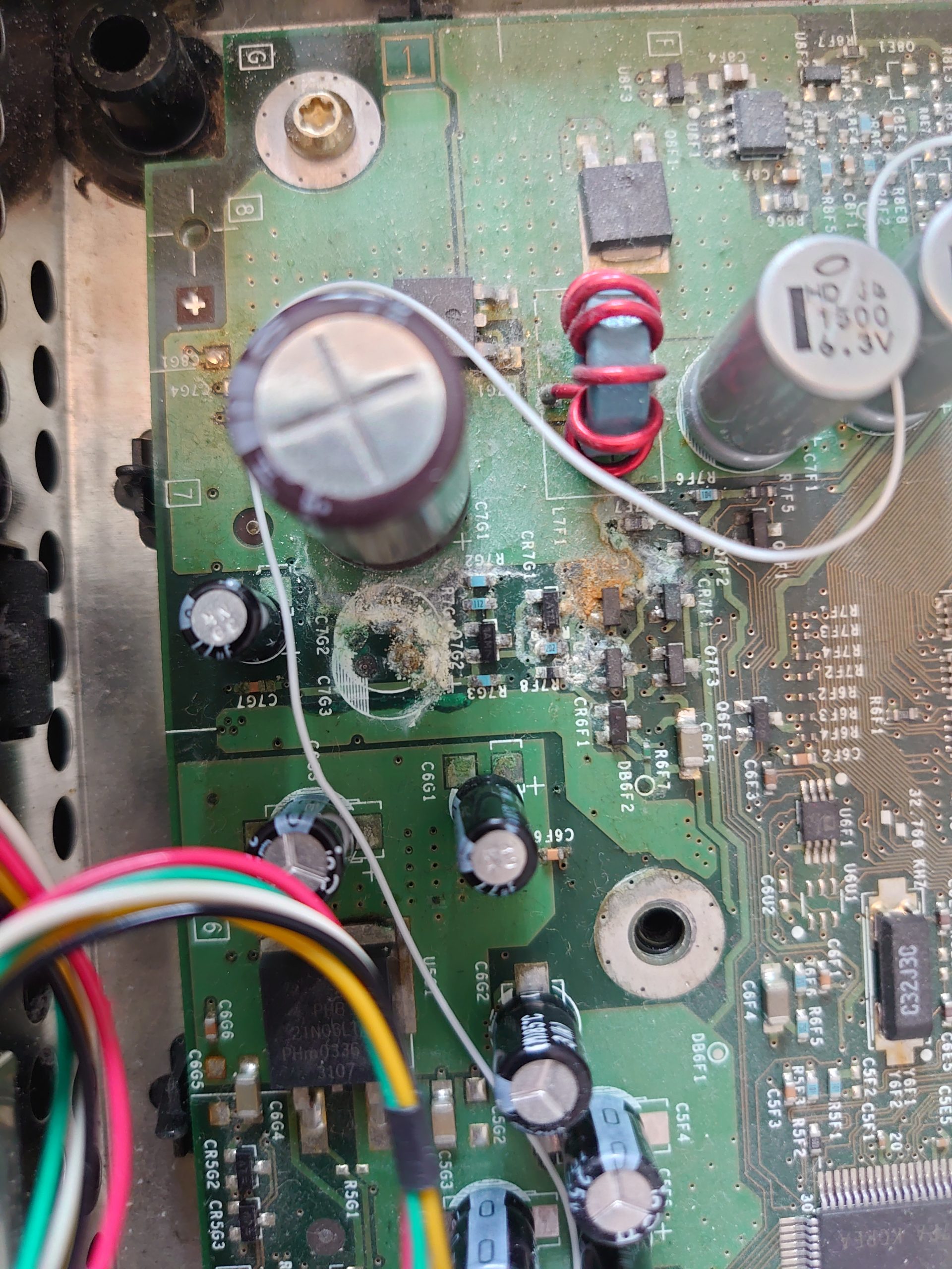
Locate the affected area.
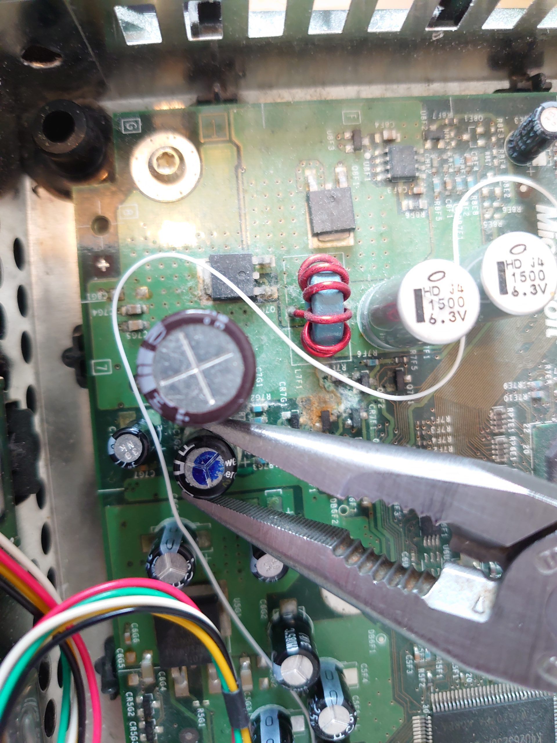
Remove the bad condensor by (gentle) force (back and forth) or with soldering tools in hand.
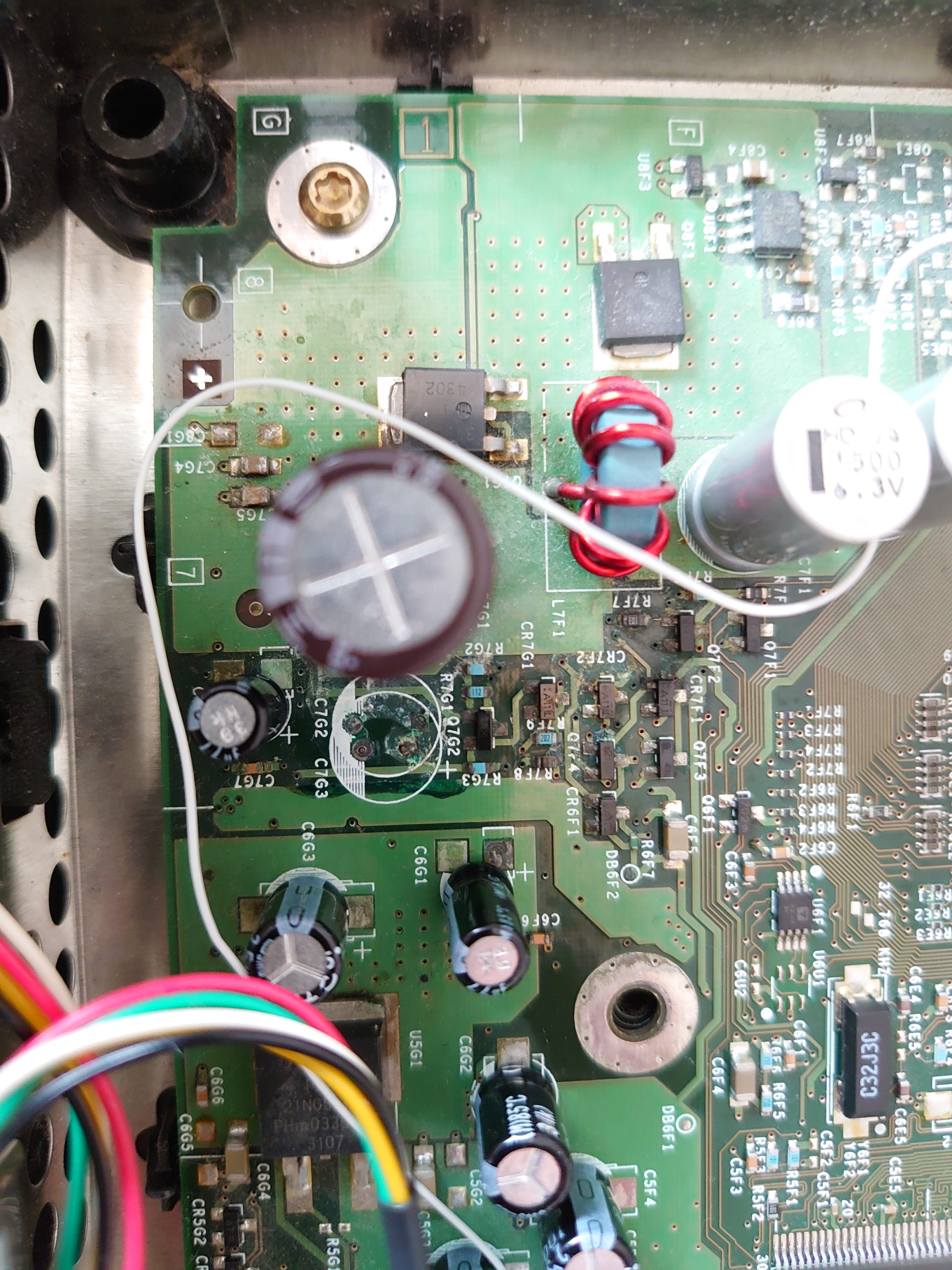
Analys the area and grab whatever you find appropriate to clean it with. Yes, isopropyl alcohol would be the best choice.
Clear. Over.
Of course we could replace the bad capacitor with a new one. But it is by no means necessarily, since it only affects the system clock to lose track of time if power cord gets disconnected.
Not a single right or wrong decision. Let your own moral be your guide in this dilemma.
Some background – I bought a Hyperkin Panorama Xbox HDMI cable to add some modern HDMI output. Sadly I realised that the picture where flickering a lot via this cable in PAL mode. Works well via s-video and composite.
After some internet searches. Everything again pointing towards bad capacitors or grounding issues. Maybe some other power issues as well (source: here)?
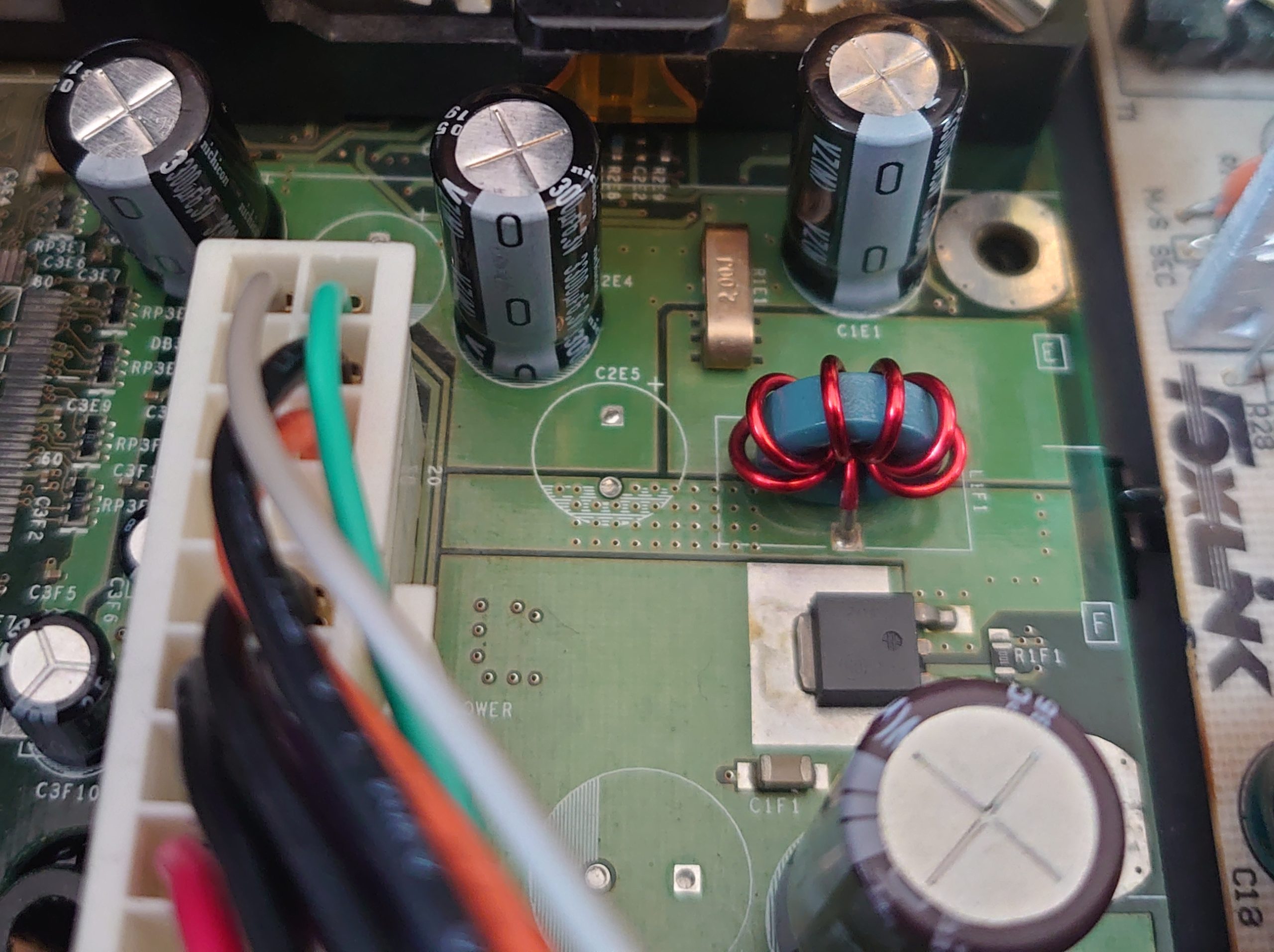
I thought the first step would be to replace the three capacitors (3300uF 6.3 V) near the GPU. So I went for it:
Old capacitors
No capacitors
New capacitors
But no, same thing happen anyway. Flickering HDMI picture. But hey, atleast I got some fresh capacitors installed.
I guess I need to continue with another HDMI cable or HDMI solution. Because a change of PAL to NTSC (via the Enigmah tool) didn’t solve the flickering issue.
To be continued…
Future ideas
– Use another cable (s-video or component) solution, and make it HDMI via a convertor.
I believe this is a post for a smaller group of (somewhat nerdy) people, so I will instead write it in English, rather then in Swedish towards the usual Swedish blog audience. Enjoy!
Page versions:
2021-11-08: First public version of this post.
2021-11-25: Installed a modified (and externally powered) USB hub.
2021-11-29: Project paused. Trying to troubleshoot why MemTest give me errors. Waiting for a new SDRAM.
2022-01-06: New SDRAM arrived, but with similar performance issues. And a CEC blocker didn't do any difference for the build. Same issues remains but when I disconnected the PS1 power unit supply (PSU) seem to give me better MemTest results.
2022-01-20: Hurray!! I found the solution to the previous power issue I had. The fix? A new step-down module (XL4005) instead of the old (🤬) LM2596.
2022-02-03: Installed the upcoming PSX core (unstable build) in the MiSTer Station. Updated the chapter PSX core.
2022-12-31: Added info about the new SNAC PSX adapter (not in this build) to the "Todo / Future backlog". Clean up in this Page version section.
2023-03-08: Updated the software parts of this page a bit. Added videos and texts. Removed the separate SAM chapter (now included in Update All)
❌ Current unsolved issues with this build
The PS1 PSU use approx 10 to 11 Watts (rate as 10 W on the back sticker). PS1 PSU output seem to be approx. 6-7 V and 1 A. Compared to the 6 to 7 Watts of the original DE10-Nano Power brick.
Solution: Works anyway. I will ignore this finding for now.
Optional: Experiment with a small fan (and fan control?). Because I almost burn myself on the CPU heatsink. Figures that this kind of heat couldn’t be a good thing for the board, in the long run.
Optional: Make the Reset button (on the Playstation case) work (maybe with a transistor solution, connected to the I/O board in pin P3?).
If this would have been built in the late 2022. I should have tried to squeezed in the SNAC PSX adapter (better latency and power handling) instead of the (sort of ugly) blue USB adapter used in my build. Please find more via the link(s) below:
In my (from time to time) series with tech DIY guides (like the earlier Pacemaker SSD upgrade, and NESPi 4), I will here post an overview guide of my latest project. I reveal to you *drum roll*…The MiSTer Station (whoops, you already knew that from the title). You also can call it a Playstation 1 (aka. PSX, PS1) dyi case mod, if you like.
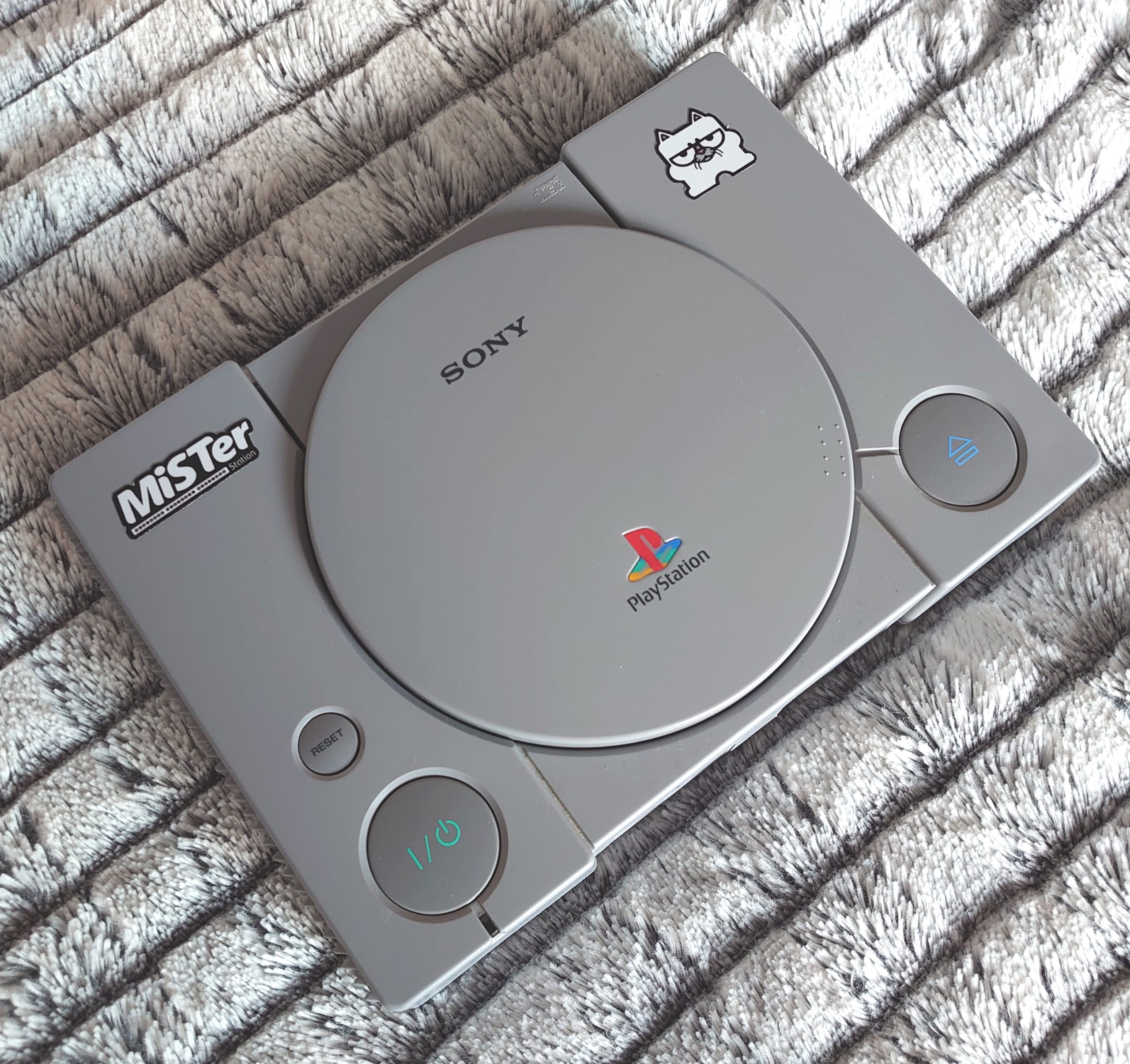
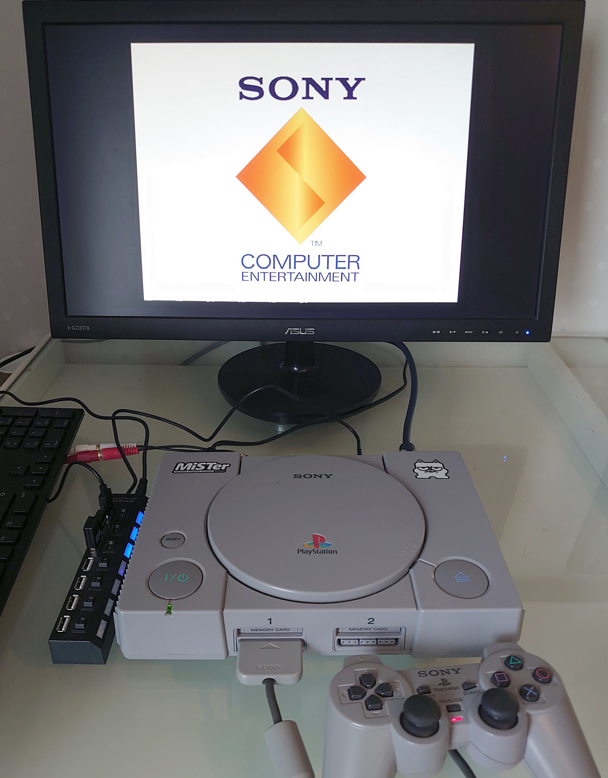
1.1 Pictures of the final result
The Mister Station case.
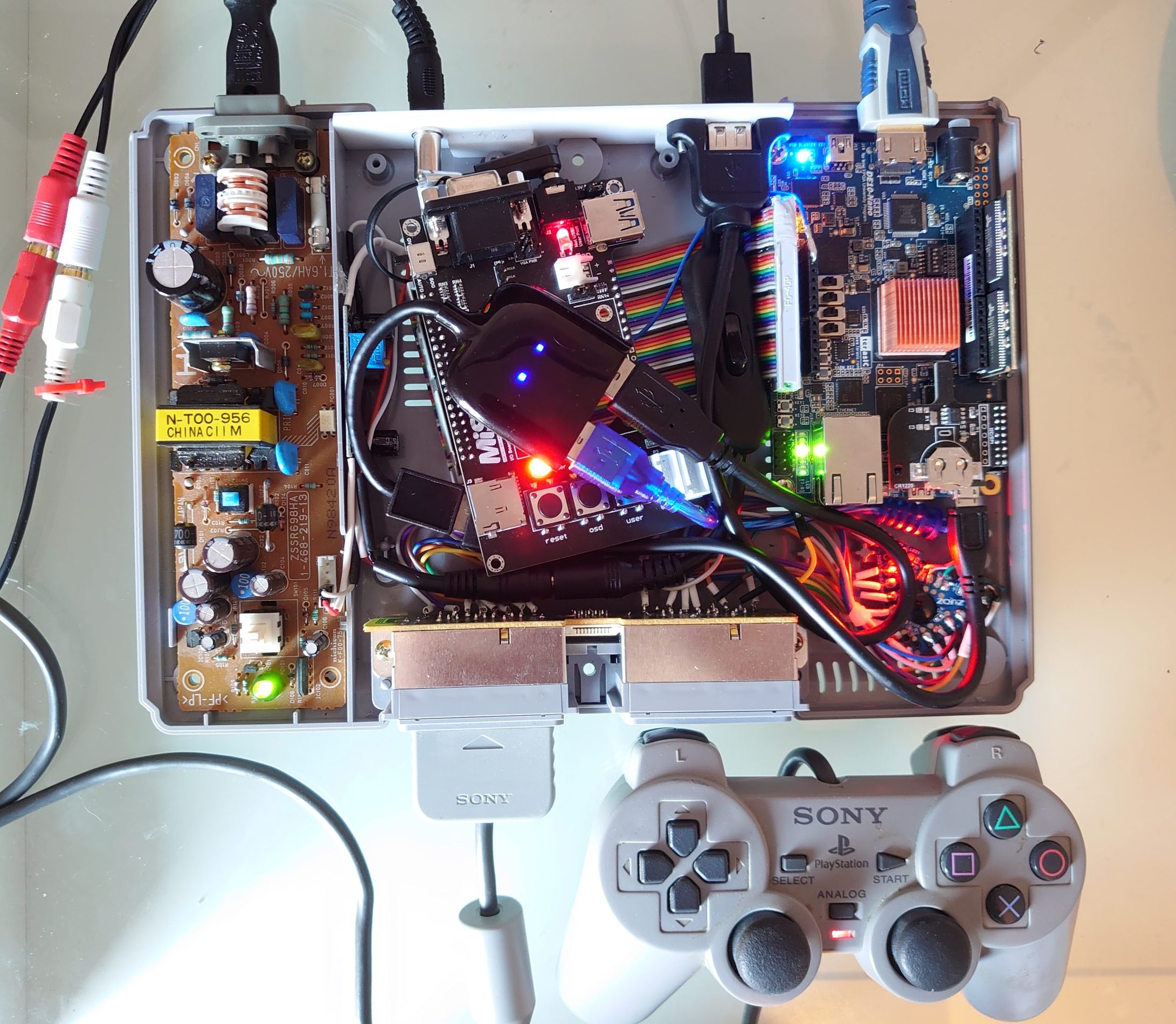
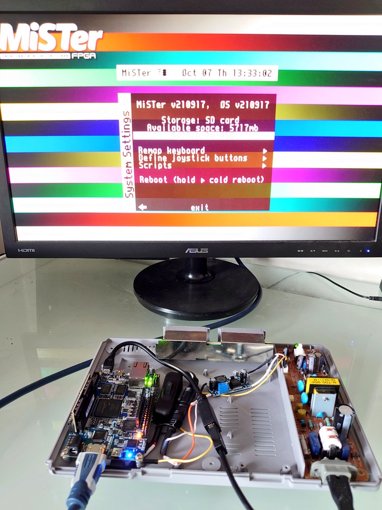
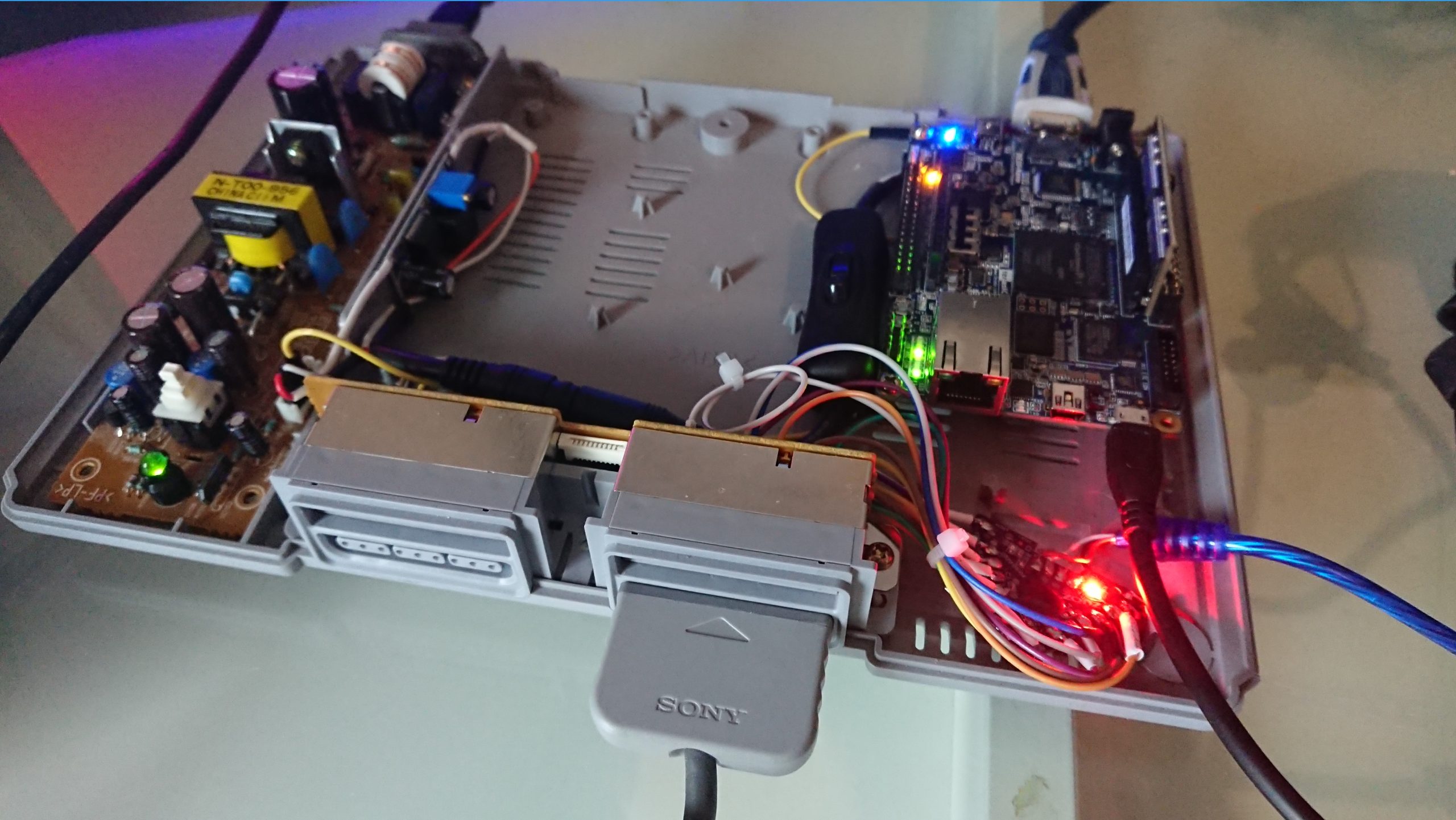
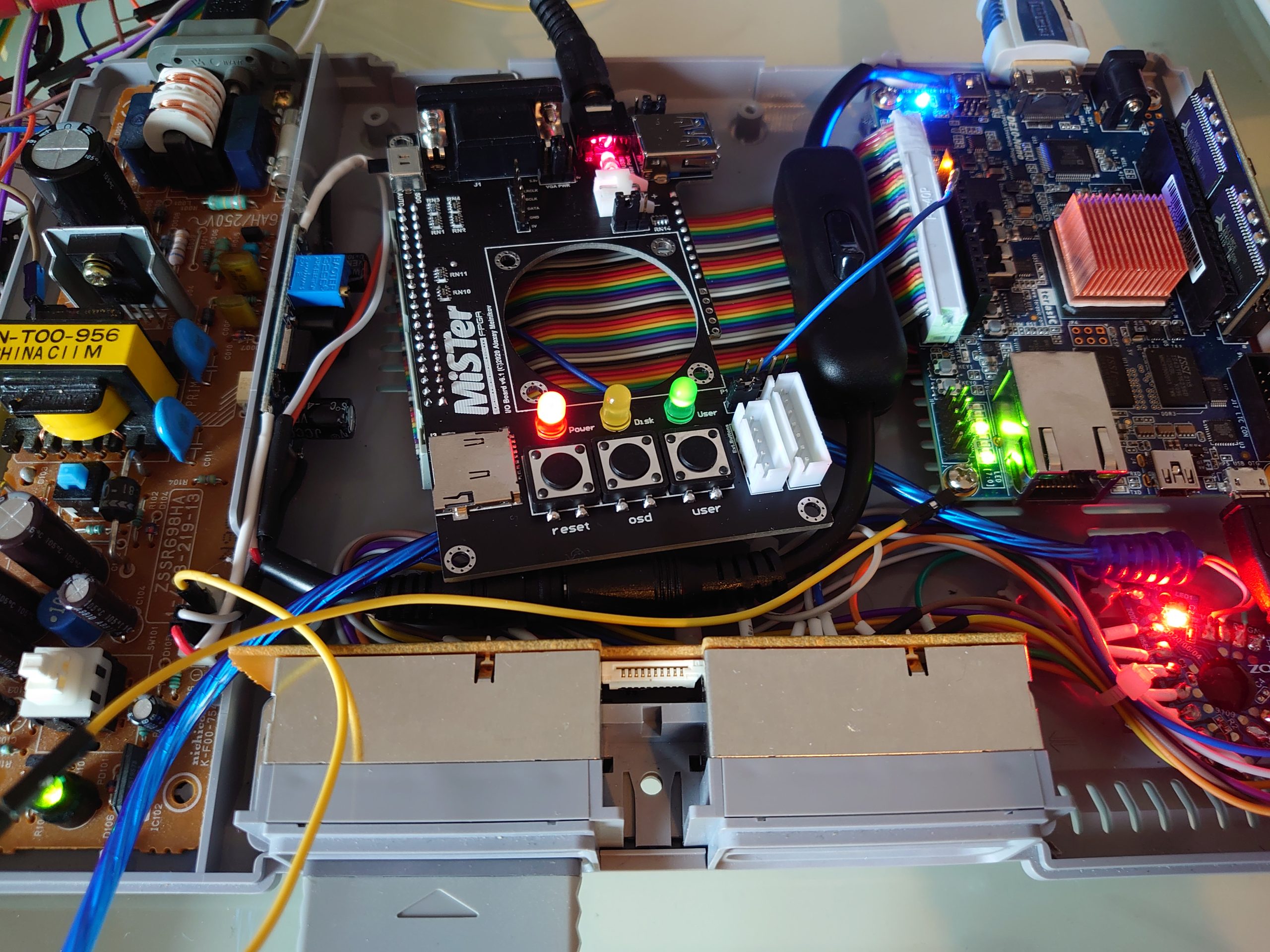
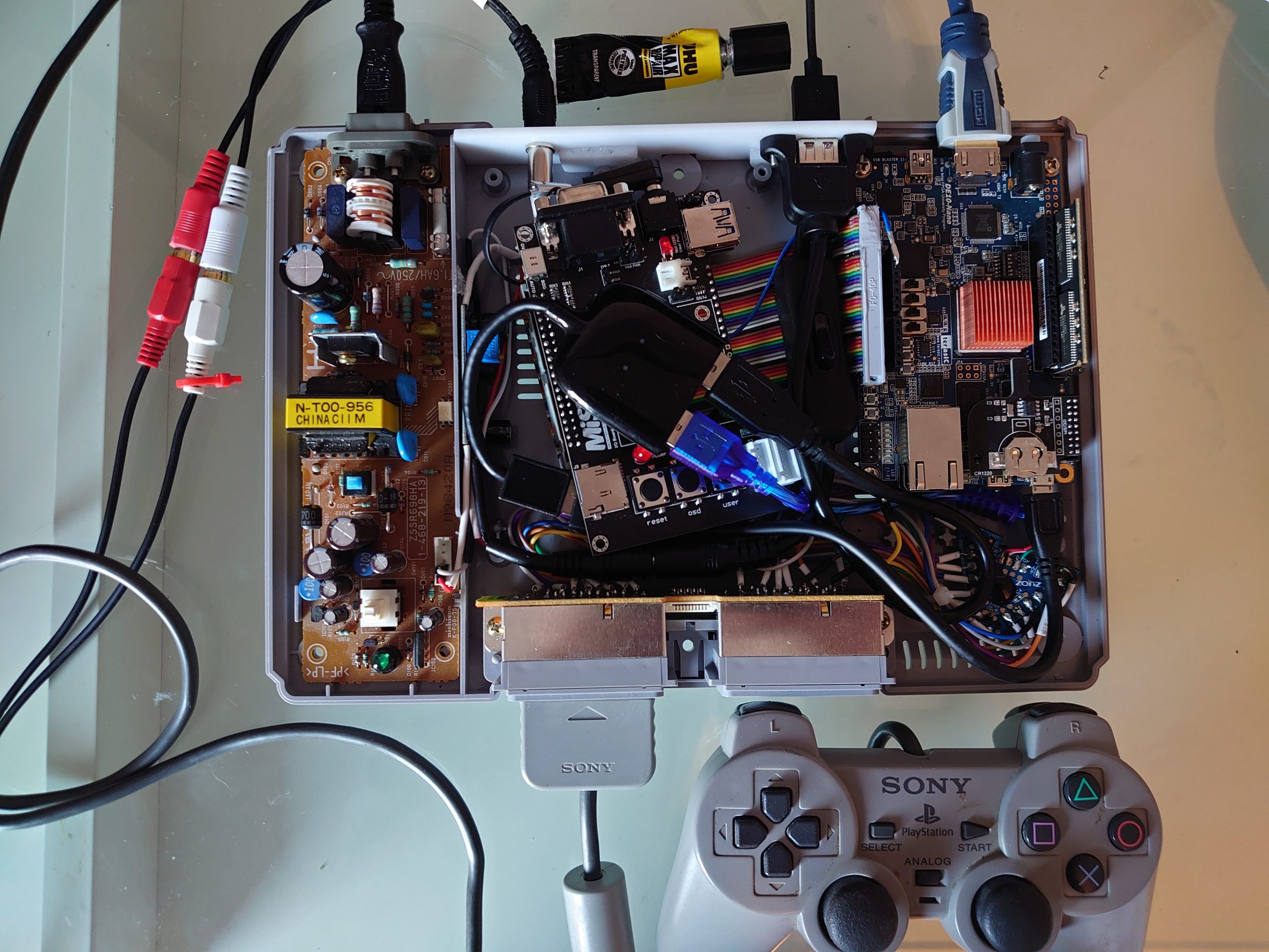
This is what a “DE10-Nano MiSTer in a Playstation” look like inside out.
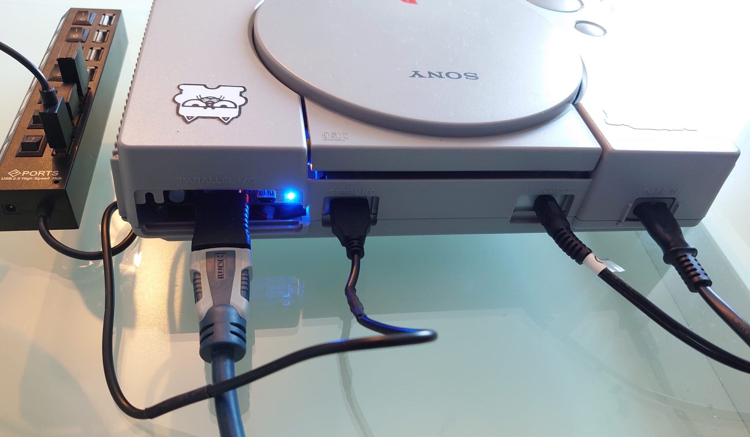
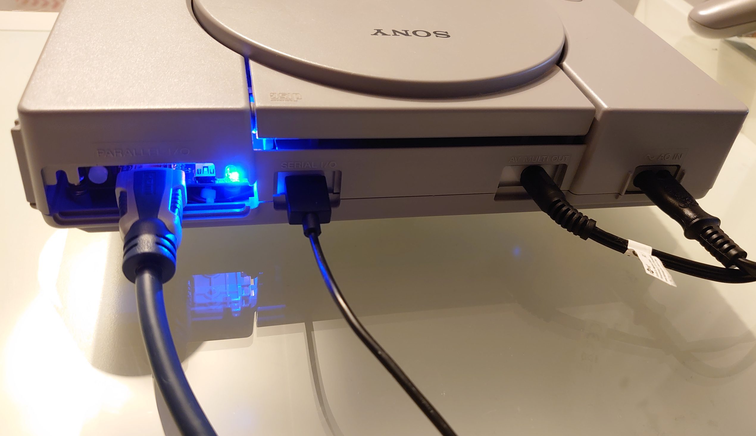
I/O on the back. HDMI, USB-A (2.0), Audio out 3.5 mm and Power in (230 V).
Running unstable PSX core in MiSTer, in the final build.
1.2 Story behind the build
Main target was to build a gaming computer in a Playstation case. With the exterial look as intact as possible but work as modern tech regarding the Input/Output. For convenience, USB and HDMI output was a minimum requirement.
With an already built-in PSU I early decided to keep this and the original power cord and PSU. This meant I was restricted to a 10 W for the internal parts.
After some research the choice fell on the DE10-Nano (5V, 2A) and the MiSTer project. I like the thought of accurate hardware as the backbone to run retro games on. Since some skilled programmers like FPGAzumSpass (Twitter, Youtube, Patreon) and Laxer3A (Twitter, Patreon) work(ed) on the PSX core. It would of course be nice if this build could play PS1 games in the future. And maybe, just maybe I could pick up some of the long forgotten PS1 games from the bottom of that old nostalgic box in the attic when this is all done.
Wait, what?! Not familiar with the MiSTer FPGA? OK, let’s start from the begin. I then recommend you to read a bit on the retro game phenomena Here, Here and/or watch some good YouTube videos on it, like this one bellow, before continuing this article:
My main concern before the start of this build was the power consumption of the Terasic DE10-Nano board, together with all the additional accessories like:
a non-powered USB splitter or USB hub inside the case.
the front port solution with the controls, and
an analogue extension I/O board.
I couldn’t find specifications for the majority of these parts before the purchases.
Playstation hardware – Space within the case.
I know that it is actually a lot of space to work with but from my previously NESPi 4 case mod (a Raspberry Pi 4 in a NES). I also know that cable plugs sticking out of the board and the cables themselves take up tremendously more space then it initially may look like.
Know-how
MiSTer project
I did know very little of this at the beginning of the build. Was there any restrictions, missing or buggy software?
Soldering
I am in no means a master of soldering so bear with me 🙂. It can take a while and the result may vary, but with some patience this shouldn’t be a major risk. In worst case I brake something and will pay extra for additional parts and just start over. For example the DE10-Nano itself (as I later on would be painfully aware of. Woops.).
Playstation hardware
In the beginning I didn’t knew a whole lot about the PSU or the controller ports. But I’m sure I will gain more knowledge during the process. The same thing about the other electronic parts, as well as the plastic case itself.
Good, now when that is over with, we can begin to look at the accual hardware and the building process.
Let’s make this look a bit more neat and not so shockingly dangerous without the top cover.
2.1 The parts of the build
As always when you try to mix things together, it is good to have a recipe in hand. Here is my list of “ingredients”, split in three parts: Base, Full & Front ports:
Base
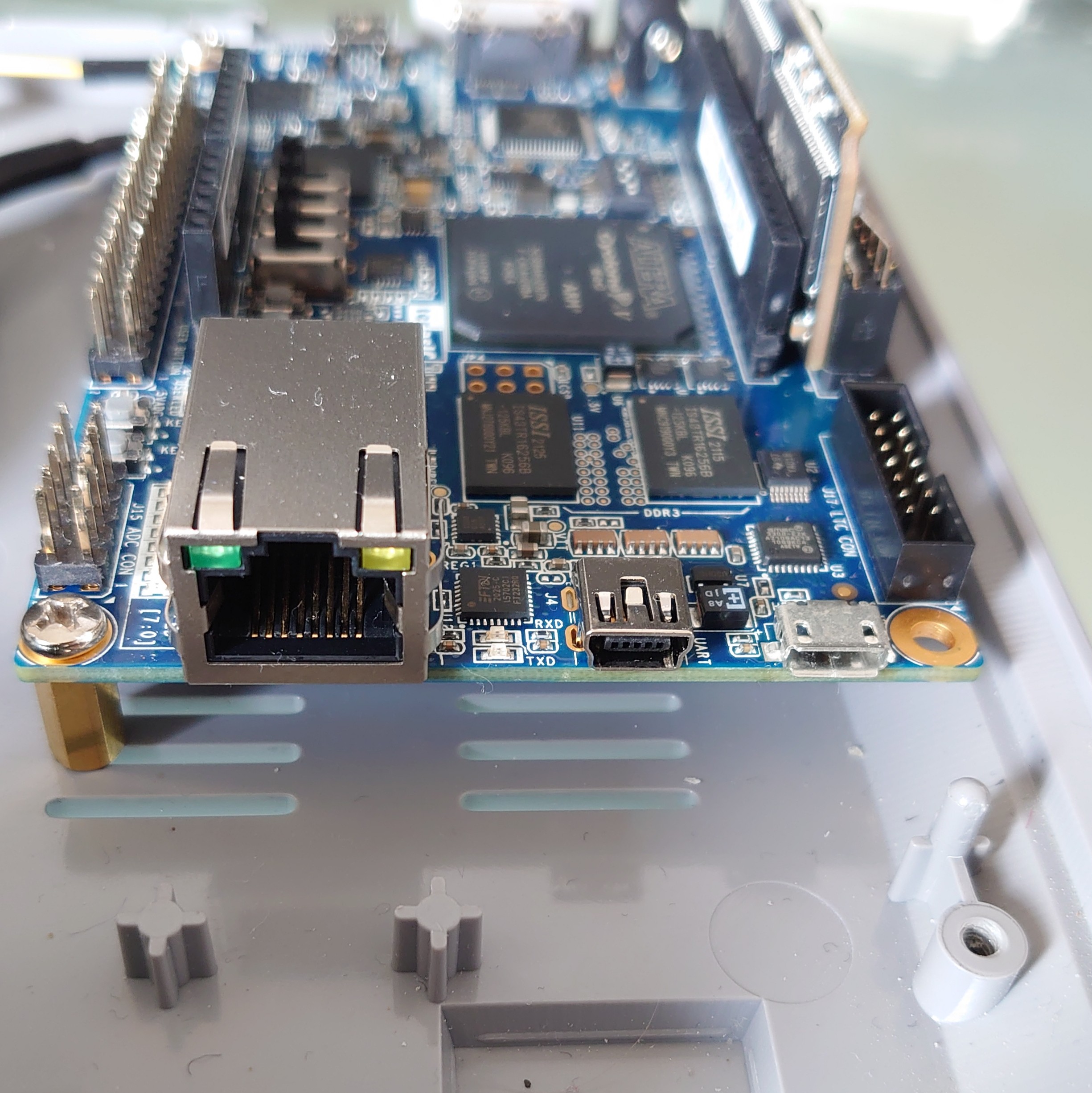
1 pcs DE10-Nano board. I tried ordering from both MiSTer addons and Mouser. The later came without smashed cover glas, so I may use Mouser again if I were to buy another one in the future.
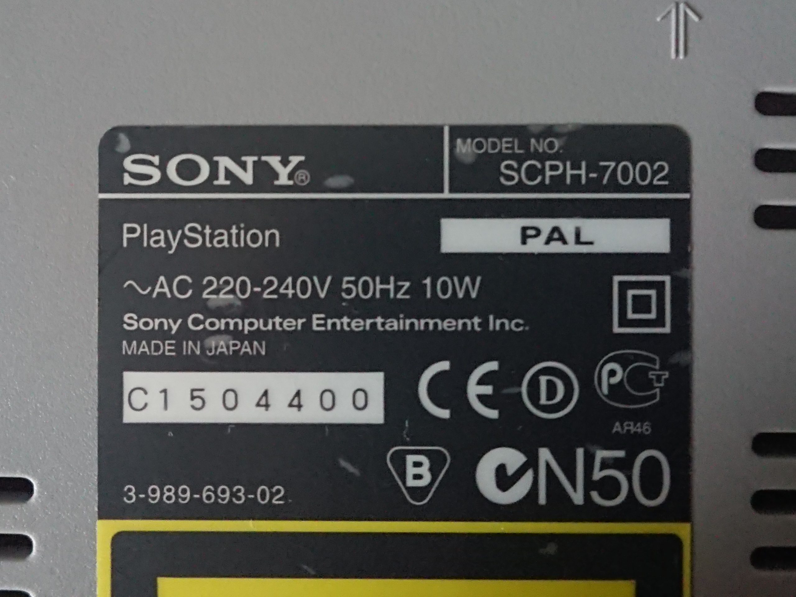
Playstation 1 console. (SCPH-7002 in my case.. pun intended)
Some sort of back plate material. (I used some sort of white plexiglas, 3 mm thick.)
Powered External USB hub (like Gembird UHB-U2P7-03). For Bluetooth adapter, keyboard and WiFi adapter. Therefore I recommend minimum of 4 USB ports are recommended.
Power cord, if you want the option to also use the DE10-Nano standard power socket for test or whatever purpose. (I also included an unnecessary switch in my build, don’t do that if you are looking for space optimisation.)
1 or 2 original Playstation controllers (of course)
Flat jumper cables. I mostly used 20 cm female – male but buy a bunch of different lengths before you begin.
2.2 How-to fit all the hardware parts in there
A good start is to begin in the late year of 1997, with a SCPH-7002 (PAL) – 220-240V & 10W.
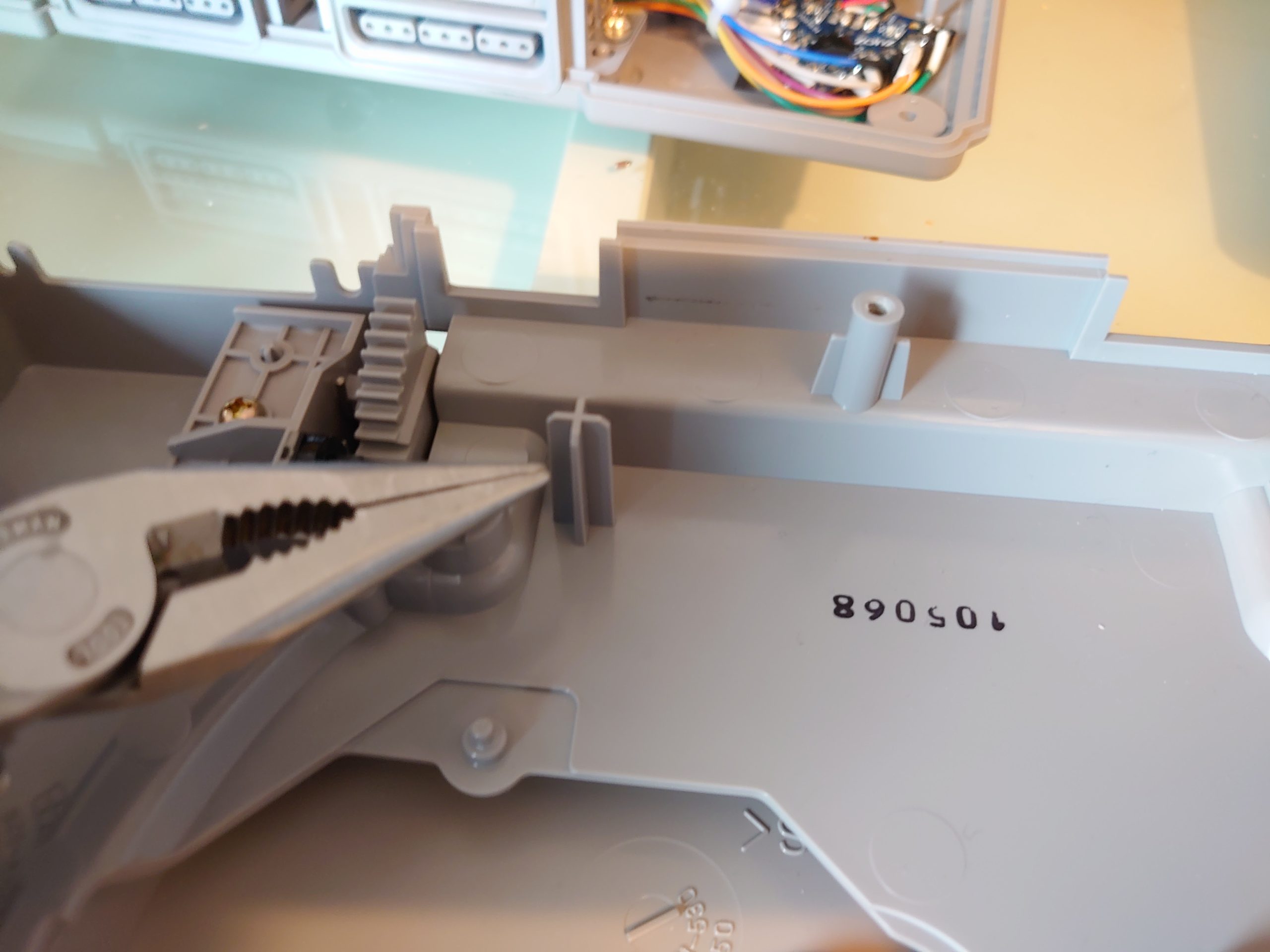
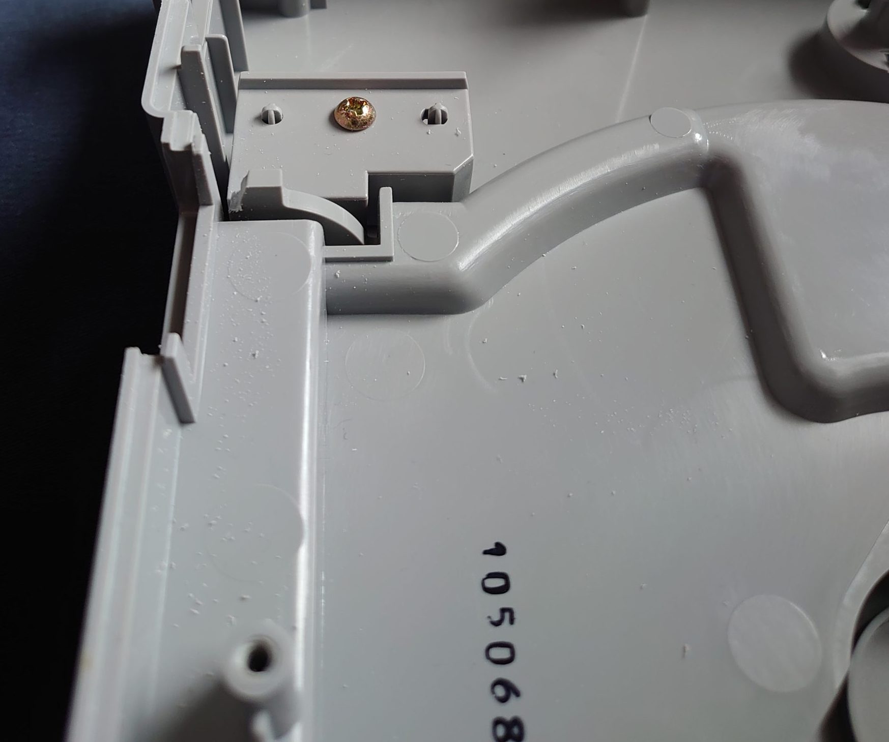
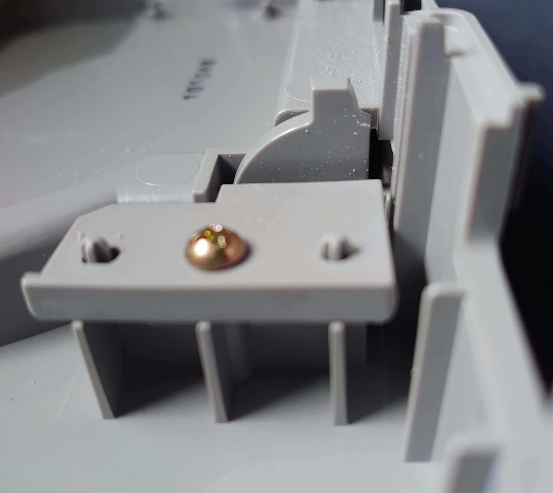
Strip it from everything electrical related except: the Power supply unit (PSU), the ports in the front, buttons and the top CD cover. Also trim the bottom plate a bit to fit the main DE10-Nano RAM module. After the picture we’re taken I also removed the little plastic rocket🚀 in the bottom center in the picture above. Reason? Because the ribbon cable to the I/O board needed the space under the main board.
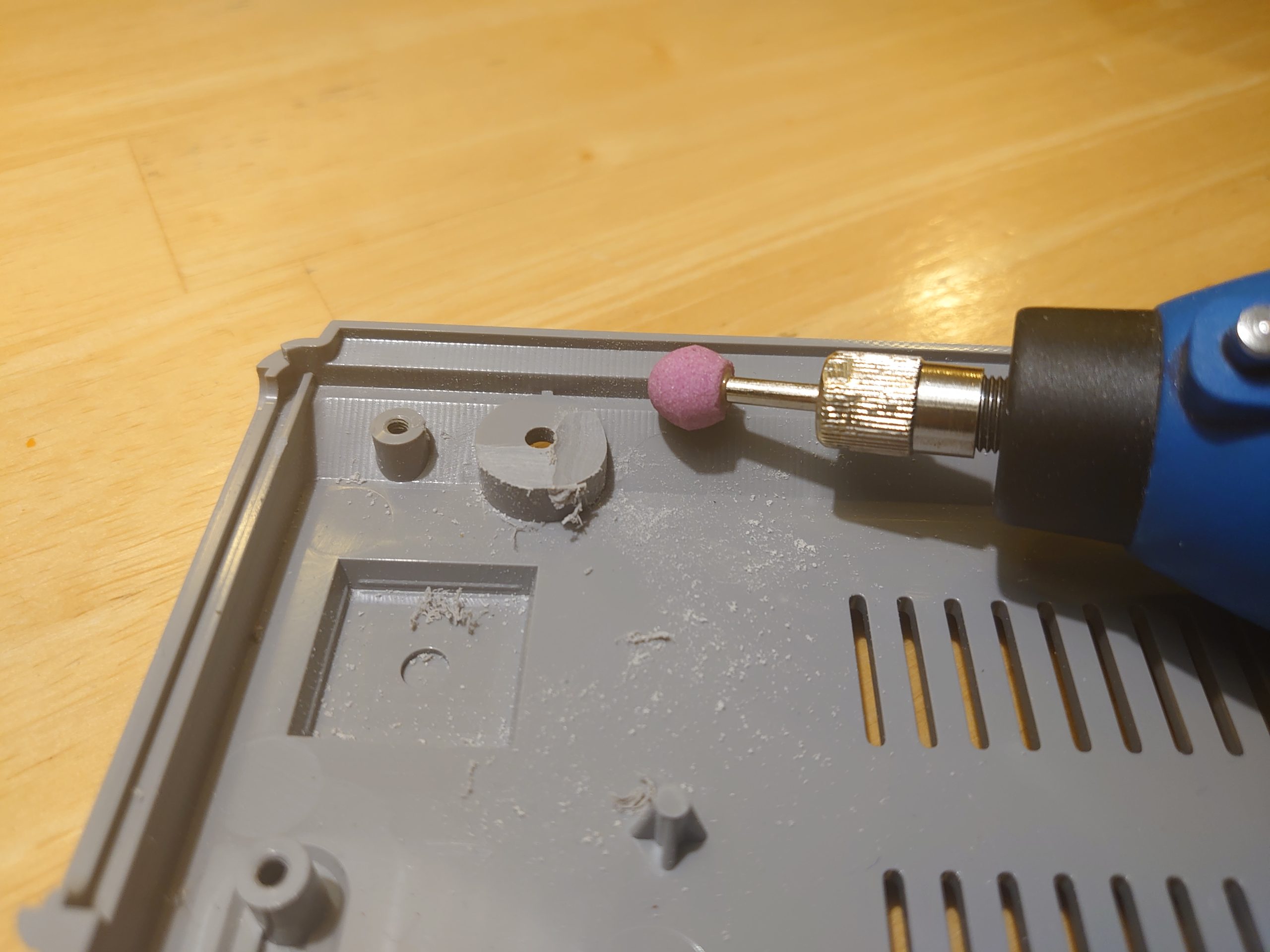
Cut this part to get more room for the DE10-Nano board and also the screw hole in the top left corner (in the picture).
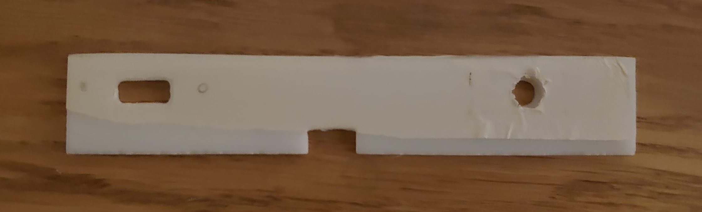
The result:
This is what I end up with.
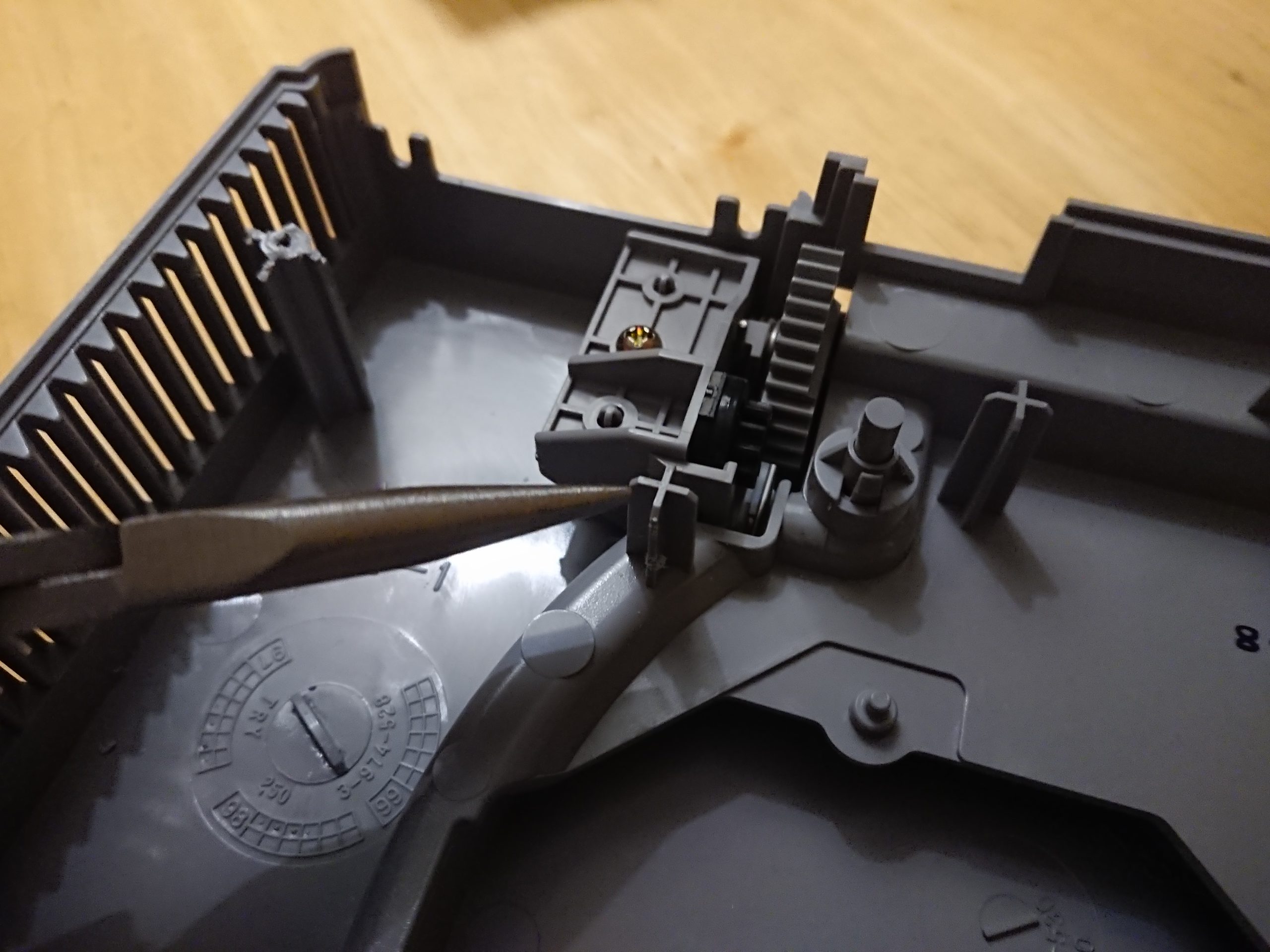
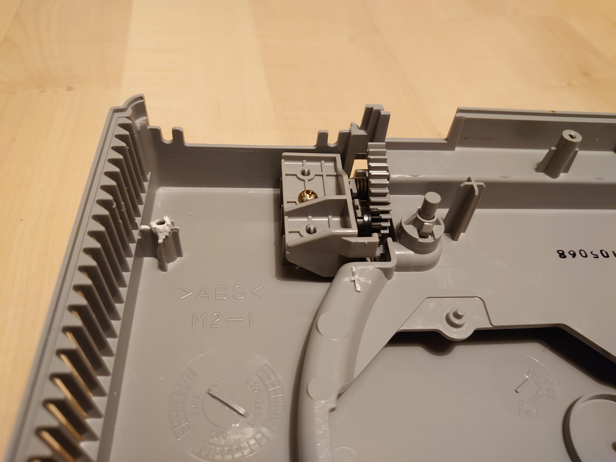
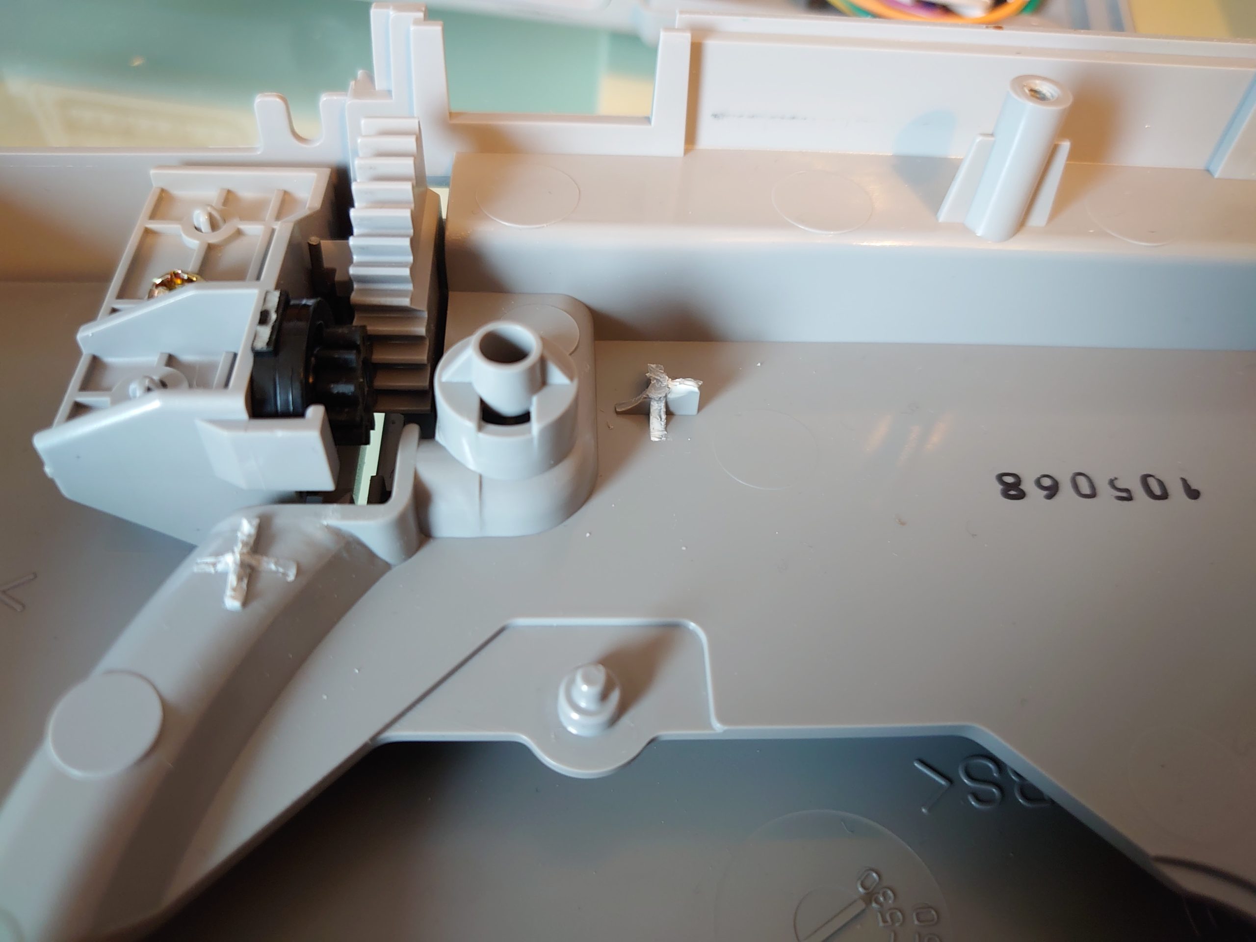
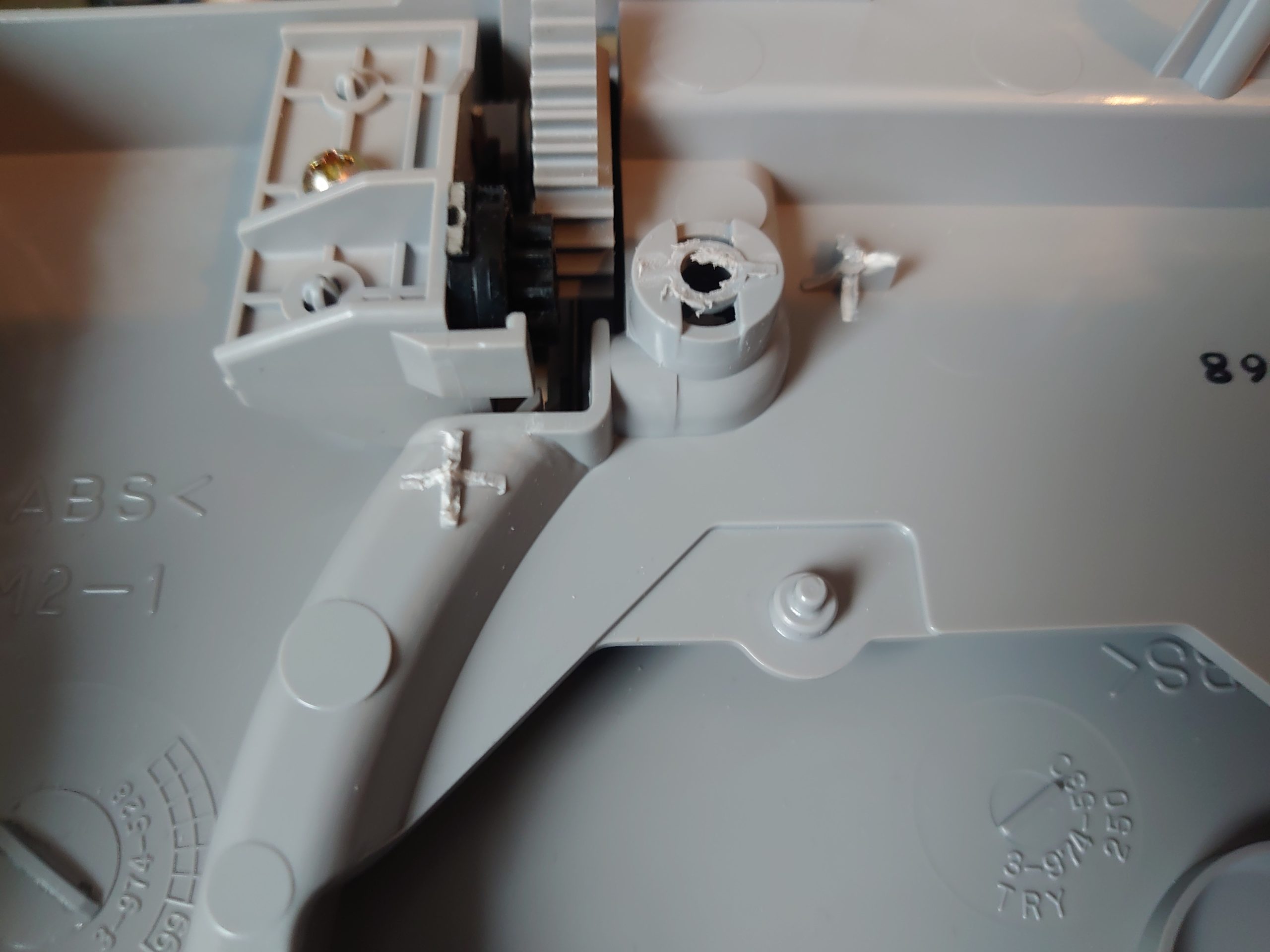
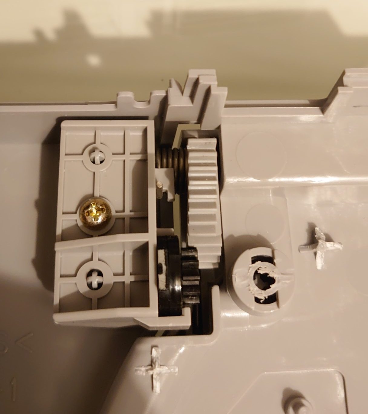
If you are going to install an I/O board and/or use the GPIO ribbon extension, you need to cut these “plastic towers” as well:
Before and…
…after pictures.
And also take the plastic pin out and cut of some of its holder, like this. Especially if you use the same USB mounting cable as me (See the chapter about the I/O back panel):
I used my Dremmel and it was an easy task. Just watch out so you don’t hit the cover opening mechanism in all this grey plastic excitement.
Power
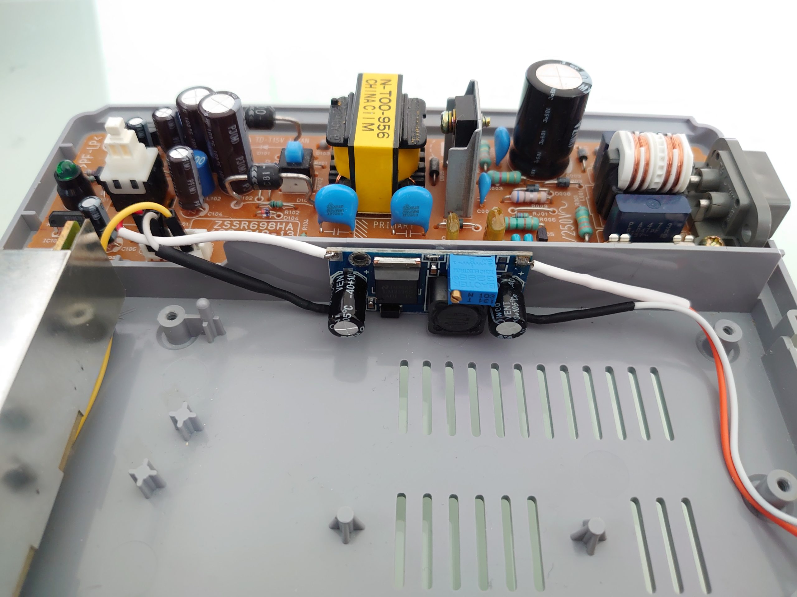
Some how I managed to kill the first board by solder these wires. So this time I did a minimum solder effort. But it did the trick any how.
The step-down module I used is a XL4005. Don’t use the LM2596 that I first used. Since it gave the build all sorts of power issues.
Down-step voltage (the picture show my old Faulty LM2596):
Making space for others parts by fasten the down-step (LM2596, datasheet) (XL4005, datasheet) to the other side of the PSU wall. The dimensions of the XL4005 is: 61.7 mm x 26.2 mm x 15 mm, and fit perfectly.
A heatsink on the XL4005 is a good idea as usual🔥.
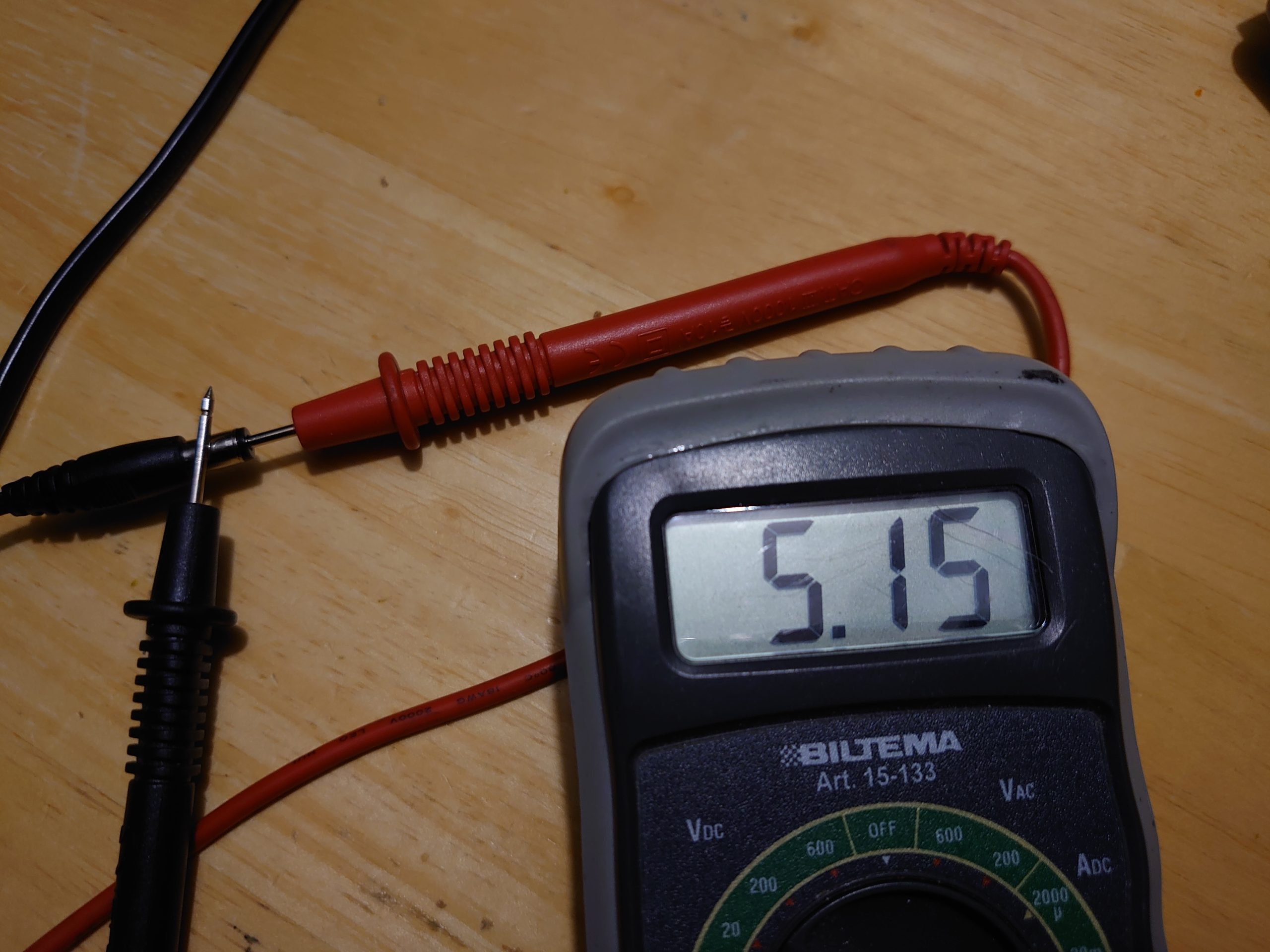
Set it to 5.15V (same as the original DC wall plug measured with my multi-meter) from 6,18 V to 7,56 V (differs from usage and measurement tool, so I am not sure here) from the PSU.
Putting two (or three) small screw brackets underneath the board to make bulky HDMI sockets fit. Also used one of the silicone feets to block the original power input.
Not to high, because the network (Rj45) port will hit the top cover. In contrast it maybe will be a good idea to keep the board a bit tight to the top part over that network port just so that the DE10-Nano can’t move inside the Playstation case later on.
Note: If you will you can use the extra space under the board itself (for cable management or whatever) like USB cable or the extension 40pin ribbon cable (see chapter for the I/O board).
Stand ofs in three of the corners make it reasonable secure. No bricks and not even screwed in to the board itself in this end.
The front ports
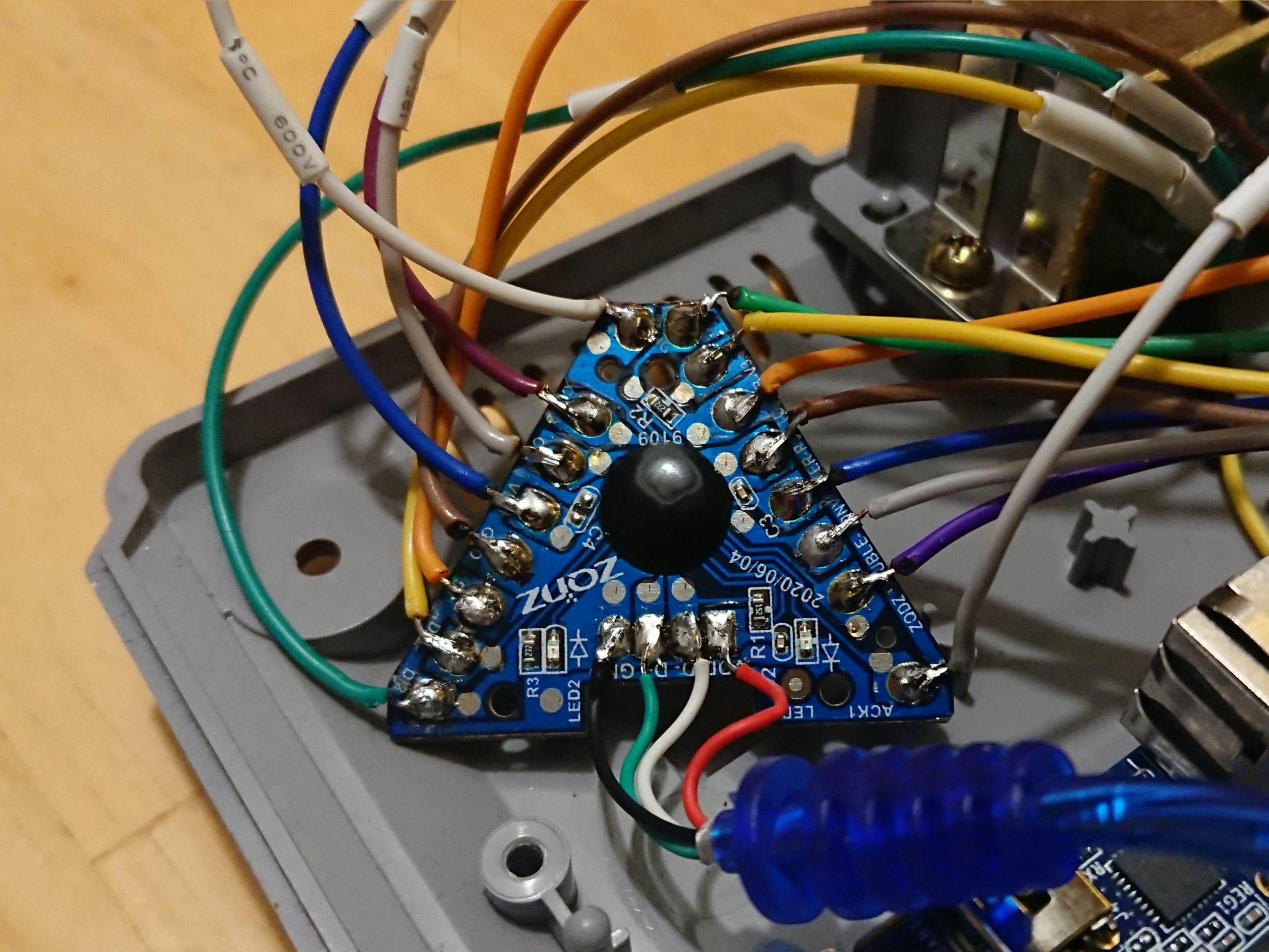
Take a deep breath and heat up your solder iron. Note that a PS1 controller (sometimes) got 8 pins but we only use 7 here (1-6 & 8). For the rest I let the pictures (A, B, C) below talk for themselves:
A) Take the blue plastic shell of the USB to PS1/PS2 -hub, and start solder some wires.
B) Take off the metal panel and follow the coloured wires to the existing solder joints in this picture.
C) I used some cable ties for a more tidy result. #cablemanagement FTW.
Power consumption
Now back to the topic of power consumption (remember my risk Power consumption?). To try out the power consumption of the parts, but mostly to stress test the PS1 PSU itself. I write my conclusions down bellow and some numbers for whomever will find it helpful:
I bought myself an EU socket watt measurement tool, and a USB Volt/Ampere meter named “Charger Doctor“. And with internal 5.15 V, (down-steped from PSU voltage output 7,56 V, but should have been be 7,4 V according to Retroconsoles.fandom.com) from my PSU (being an EU plug running on 234-237 W), it show me these results:
The MiSTer (DE10-Nano with 128 RAM) with that PS1 PSU (with attached LM2596), use around 8,60 W (idle), 9,15 W (max) during startup, without any USB devices plugged in. With a USB adapter (micro to USB-A) adds 0,16 W (total 8,76 W). Adding (to the adapter) a non-powered 2 ports USB-hub lower the Watts to a total of 8,52 W. If I continue to add my blue PS1/PS2-hub (2 ports) to the USB-hub, it will use a total of 9,39 W (idle). Adding one PS controller (SCPH-1200) adds 0,03W and adding another (SCPH-10010), adds 0,44 W to the equation. Only one SCPH-1080 controller connected adds around 0,18 W. Note that I have not plugged in the HDMI nor started anything from the start menu during this test.
If I do so and start the DE10-Nano without USB devices connected but with the HDMI attached, it use 9,35 W (max) during startup, and 8,95 W (idle).
Also worth noting is that my BT USB dongle (CSR 4.0) adds almost 1 W when it is plugged in (while searching for devices to be paired with).
Only the PS1 (SCPH-7002) plugged in, not started will use 1,06 W.
The usb-micro port outputs ≈4,6 V with my 2 ports USB hub connected (with empty ports).
Also, if I add the down bellow I/O board (+ USB hub, HDMI, Analog audio cable, Front port hub and a SCPH-1200 controller.) it will reach over 10W (10.5 W) during start up sequence. But it seem to work fine (even under the pressure of some SNES Super Mario World play).
The test:
[Warning and disclaimer]
I did this so you don’t need to. It might be a bad idea to load the Playstation PSU this much.
This test with my old (incompatible) LM2596 (down-step module).
How I did it: I ran MemTest to get a max load on the board.
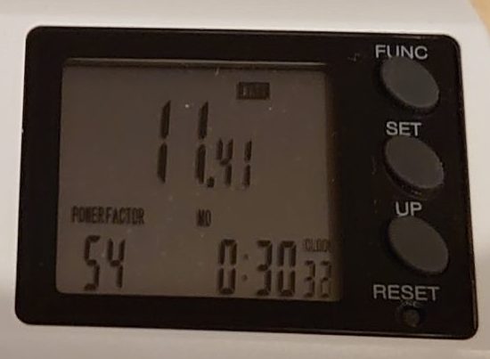
Start value at 10,98 W and the Max power consumption (watt/effect) at the end of the tests were 11,50 W.
Picture of the watt meter after testing in 30 minutes.
Analogue I/O Board
A good to have road map, to any electric DYI build, is the schematics. For the IO analogue board v.6.1 you can find it Here.
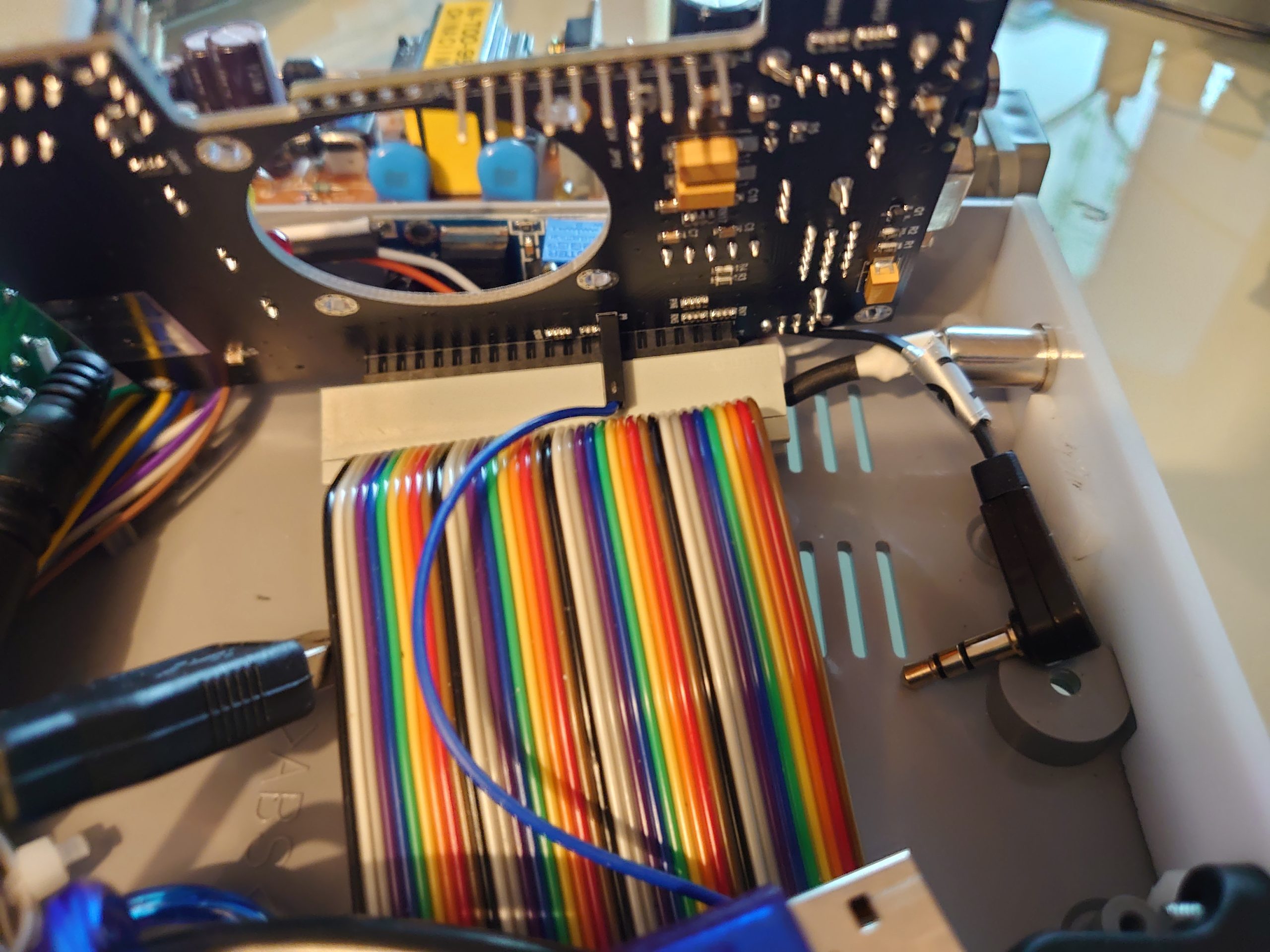
I/O board added by a GPIO extension cable.
Removed the fan for space optimisation, reduction of moving parts and effect efficiency. I added a heatsink, because – could not be a bad thing.
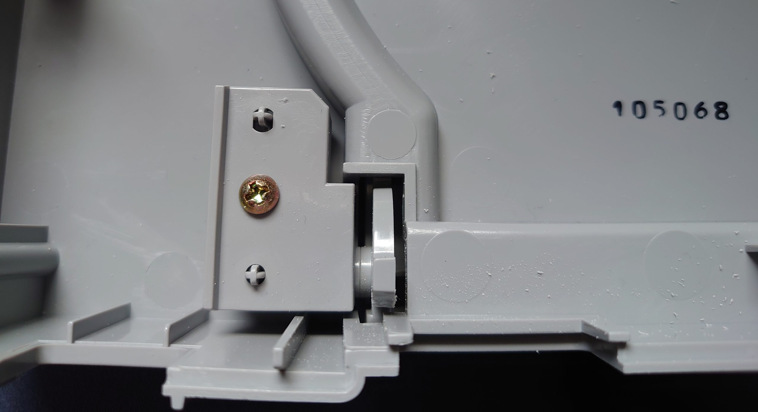
One issue. The eurorack/ribbon connection doesn’t fit if we try to put the top cover part on. Solution 1: strip open mechanism of the case so that the CD cover will be unable to open. Not a nice one, so I went with Solution 2 instead which is modification of the ribbon cable like this:
The black cog wheel is stuck on the GPIO connector. Sorry for the bad picture. I guess you just have to believe me then.
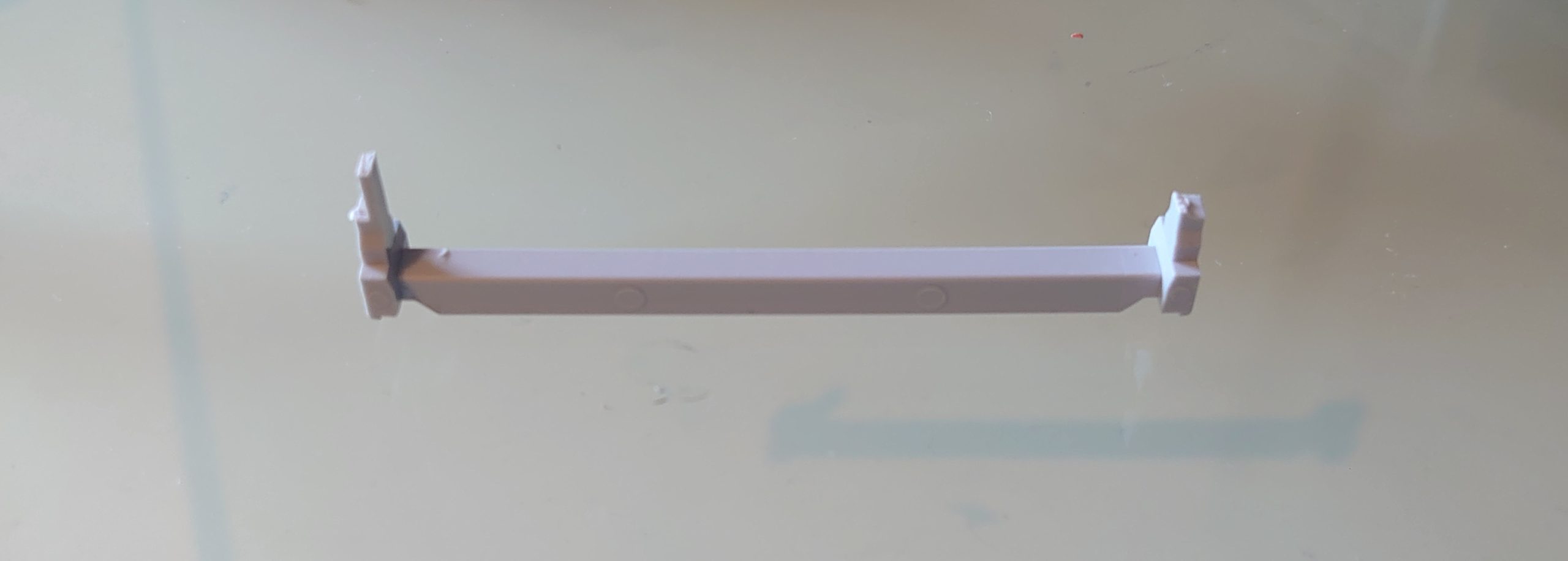
Modified ribbon connector:
By force (and no finesse) I removed the top part of the ribbon cable. This is the leftovers.
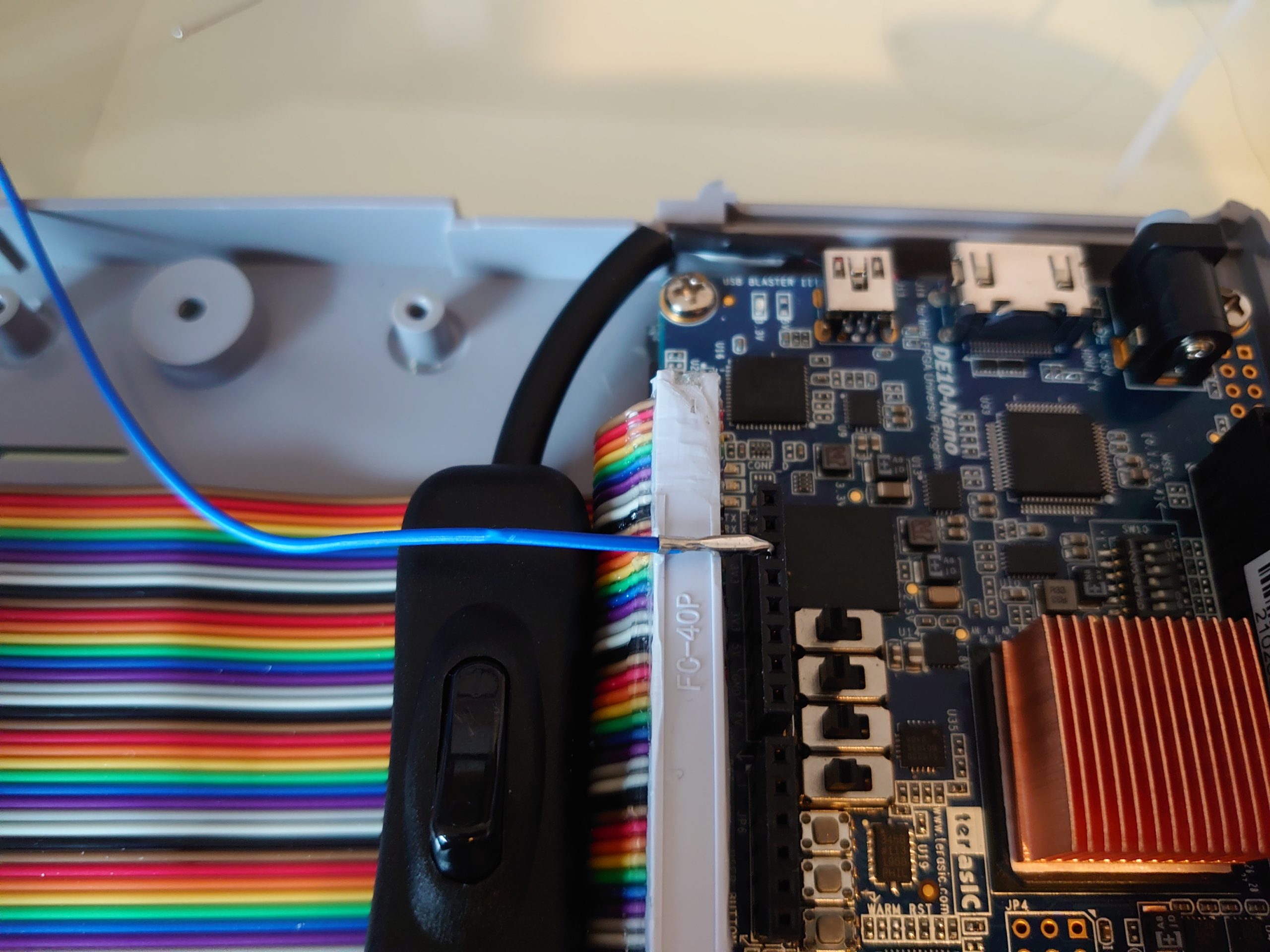
Took the top part off with a sharp tool and cut and filed the rest until it no longer touches the black cogs. Also plugged in the ‘Arduino_Reset_n’ pin to the P9 pin on the I/O board with a special designed (a bent pin without its black cover) jumper wire (male to female).
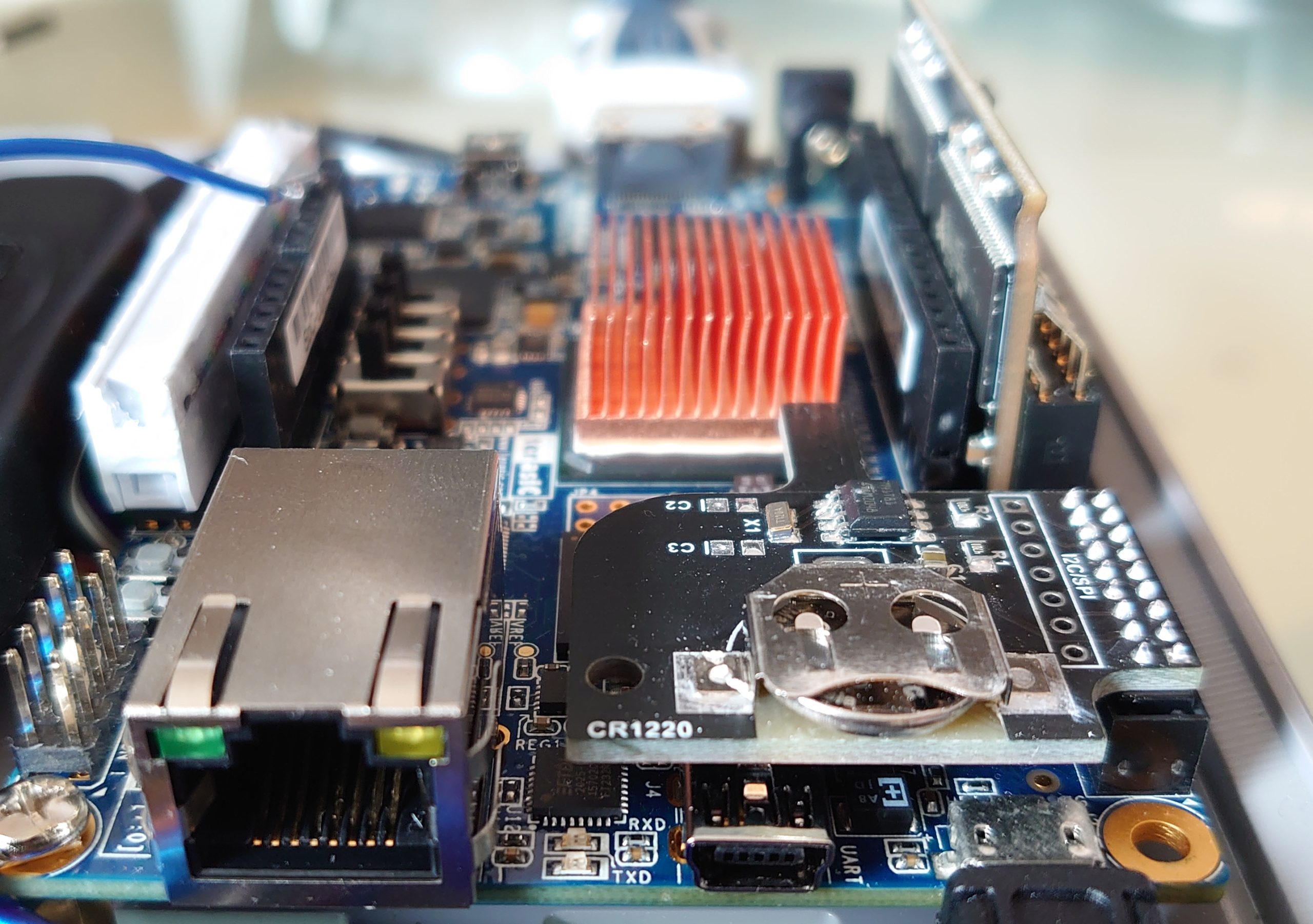
Picture of the P9 pin on the backside of the I/O Board 6.1 (analogue edition). And since Internet seem to lack pictures of the bottom of MiSTer Analog I/O and the connection underneath it, I will just put this one here. You are most welcome.
Picture of when the Pin 9 is plugged in.
OK ..I confess, this is a bit overkill for me to put an I/O board like this inside the MiSTer Station. Because it is mostly for the audio out functionality this sounded like a good idea in the first place. But hey, this is more “retro proof” (opposite of future proof) this way with the analog video out in there in case of emergency. I will go full retro someday. The audio out port is worth it anyway now that I can only need a computer screen and some sort of headphones or audio receiver.
Added a Real time clock (RTC v.1.3) as well.
Now I got an other problem. The USB adapters, USB hub and USB cables take up tremendous amount of the space left in the case. And I haven’t yet got the back ports in place. Time to be creative.
Mounting I/O ports to the back.
This is what we are aiming for.
First we need to add and create a new back plate for the I/O of your choice. In my case: one female USB and one female 3.5 mm analog audio out.
Start by find yourself a plastic/plexi board of that you have available.
Then saw/cut/file it so it will fit perfect in the case. As high as possible, put still low enough so we can close the case all together.
When you are going to close the top CD cover, you might realise that it doesn’t close properly. It is because the tight space here:
Before the minor fix for fit the back panel.
It is to narrow to the back plate, so I recommend you to cut in the case itself rather than in the home made back cover. End result after some dremel work:
Top view after the plastic surgery.
Side view #1 after the modification.
Side view #2 after modification.
Back panel in the making. With tape to make it possible to mark where to cut.
Back panel outside of the case.
Drilled holes to fit screws and audio jack. Incl. drilled sink in holes for screws not sticking out to much from the white plastic. Glued extra pieces of plastic as support of the later force of cable insertions.
Glued the back panel to the case and together with some magic of cable management, it look like this.
At last I needed to eliminate a grey cog of with my Dremmel. Just to be able to close the CD top cover lid, and not hit the inside of the USB connector (also carved in the black plastic of the USB, next to the screw as well, just to be sure).
Before the makeover.
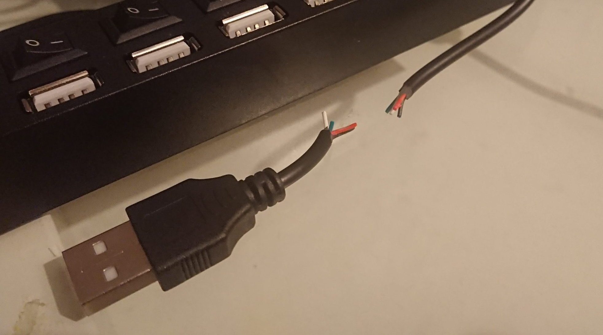
2.3 Power vs USB hub. (Aka installing USB hub without back powering the MiSTer.)
One new issue appeared when I connecting my powered (5V 2A) USB 2.0 hub (Gembird UHB-U2P7-03) to MiSTer/DE10-Nano (incl. LM2596). When I shutdown the Playstation PSU the MiSTer didn’t shutdown with it, due to the 5V via the USB hub.
The solution?
1. Cut the USB hub cord in half! 😆
(…or just cut the red wire inside of the cable, if you are not going to use shrinking tubes as I did.)
2. Then solder it together without the red VCC +5V connected. See the USB pinout schematic for details.
3. Test the wires so there isn’t any shortages.
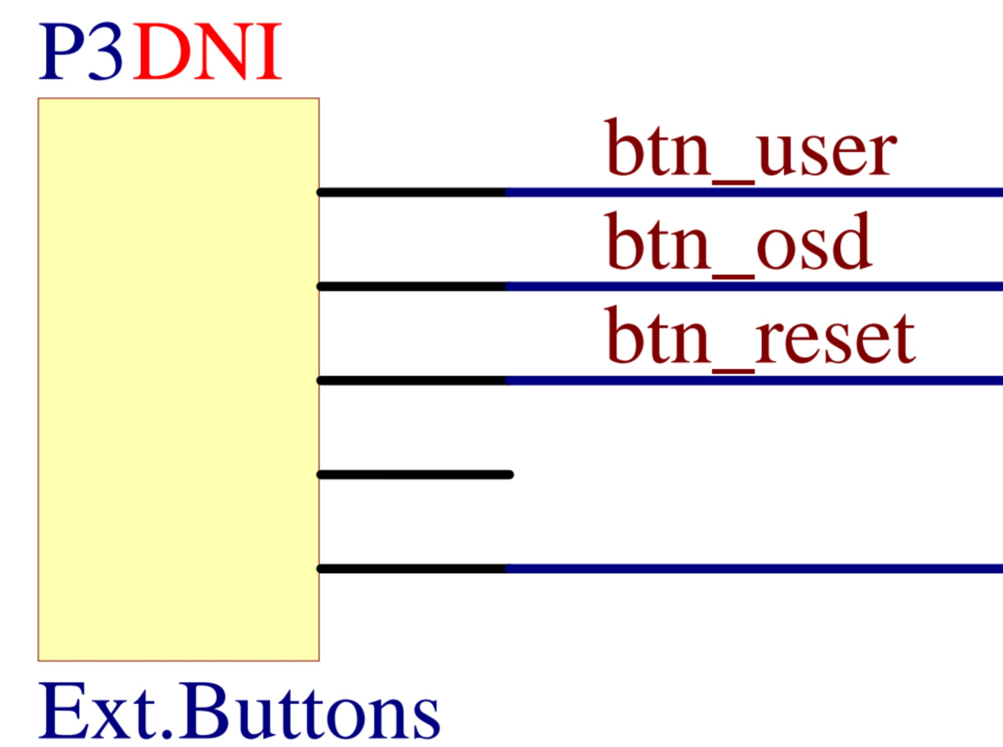
2.4 Reset button
Not yet finished – But the idea is to control the I/O board P3, btn_reset pin3 (=pin 17 on GPIO1) & GND pin5, with a transistor (2N2222, datasheet) via the Playstation PSU (7,56 V pin1, & GND pin5) when activated by the momentary reset switch.
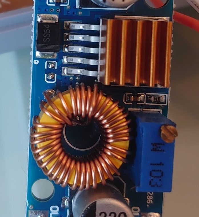
Heatsinks – Tring to handle the heat in the somewhat closed case.
The first step-down module (LM2596) I used failed, maybe due to heat. Because the MemTest performance seemed to affected by open/closed top CD cover/lid. During the troubleshooting process I switched til a better working module (XL4005) and at the same time put a heatsink on it just in case.
Heatsink on the step-down (XL4005) module.
Before this step-down module replacement from LM2596 to XL4005. I ran the MiSTer MemTest for with an open CD top lid/cover. And it seemed stable first at 122 MHz (after about 2.5 hours). I then closed the lid and it first ran at 122 then down to 120, and finally ended up at low 110MHz.
During the troubleshooting I got informed by Nat from https://MiSTerFPGA.co.uk/, that the “fastest any core needs is 126Mhz, if the speed never drops below this it does not matter.
The only core that even requires 126Mhz is the Archie core (Acorn).” – Nat
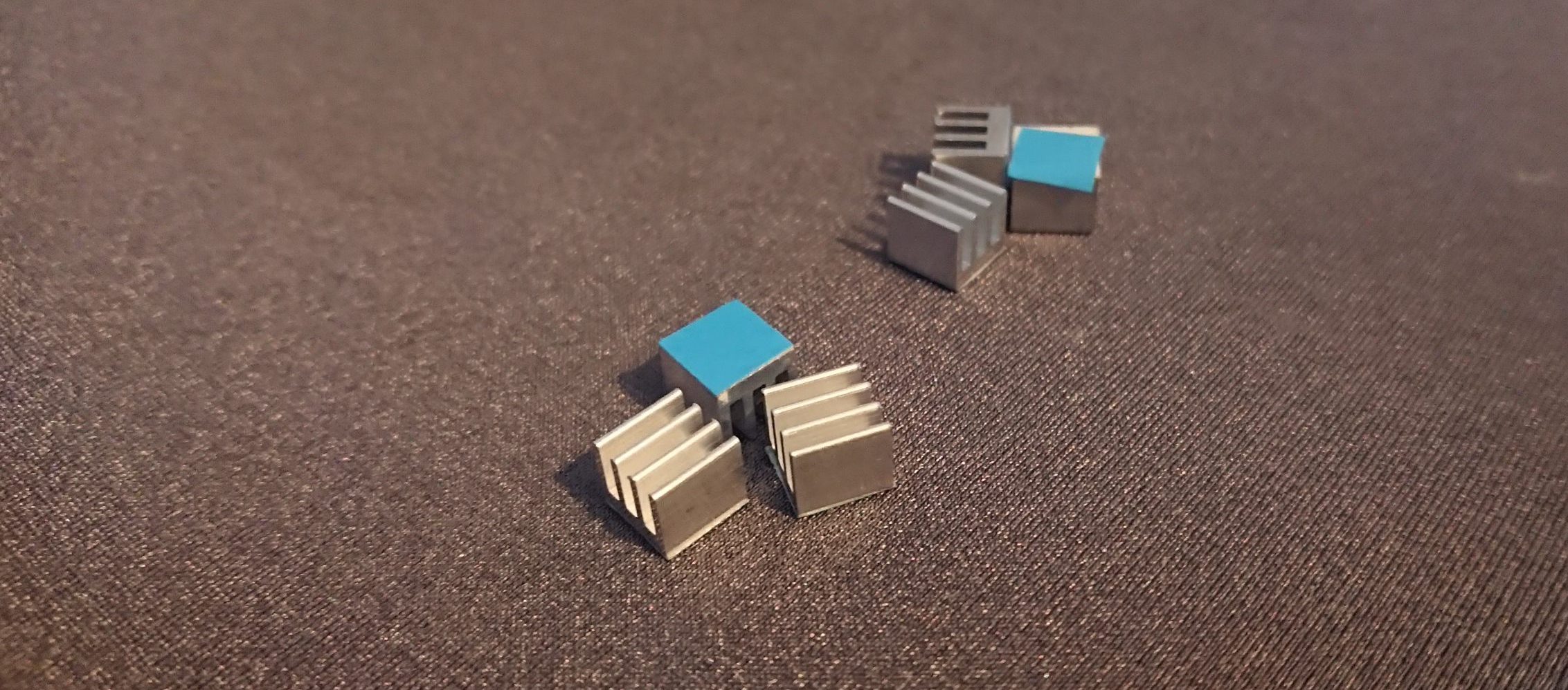
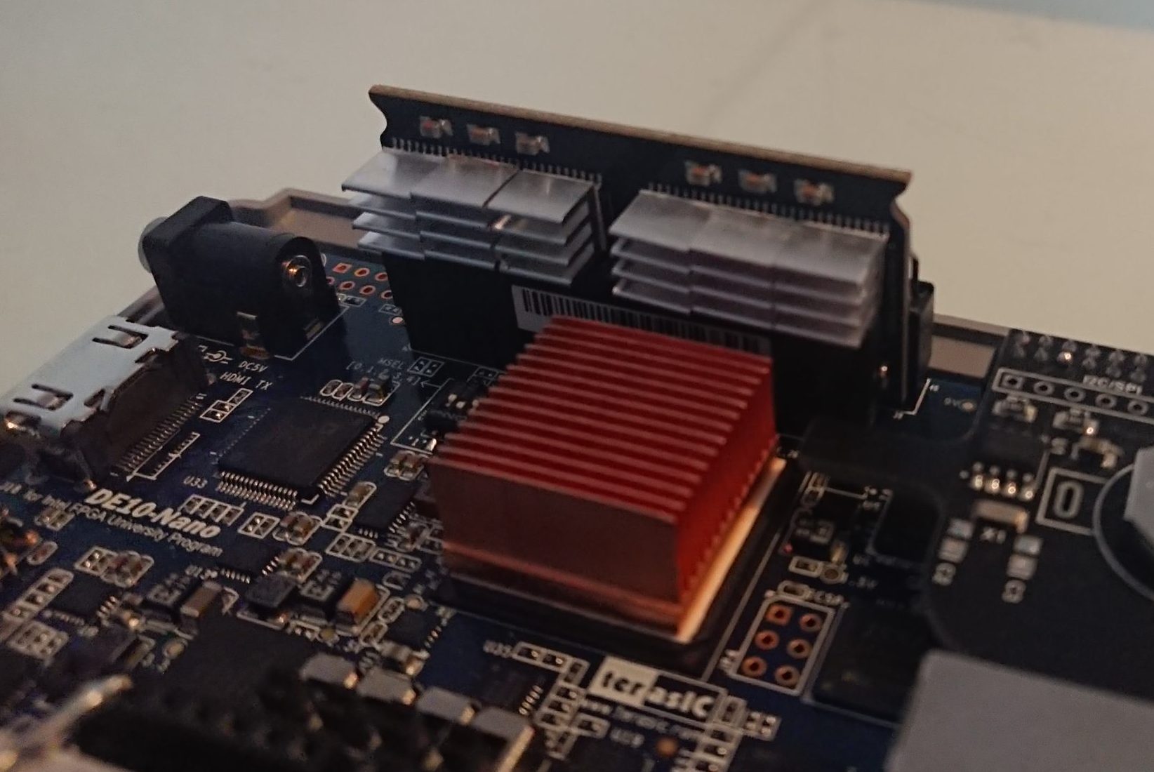
Later findings showed that it where not heat on the SDRAM that failed MemTest. Since the issue disappeared when I didn’t use the PS1 power supply unit (and also with a new down-step module XL4005). But since I already used RAM heatsinks in the troubleshooting process I will show them here if anybody is interested in this for themselves:
6 aluminium heatsinks (7 mm x 7 mm x 6 mm).
Heatsinks on the 128 MB RAM module.
[Future/Optional idea] Use of a fan.
An idea is to later on experiment with a chassi fan to find out if it does any difference to the heat of the CPU/FPGA.
A fan like this one will fit the sides of the PS1 case (along the side wents):
SEPA MFB25B05 Axial fan 5 V/DC 23 l/min (L x W x H) 25 x 25 x 6.5 mm https://www.conrad.se/p/tru-components-vippstroembrytare-tc-r13-90paa-01-250-vac-10-a-2x-avpa-lasande-1-st-1587546
If you are like me, sitting and waiting for tech parts to arrive to Sweden in the year of 2021, you can always do a lite custom MiSTer logo in the meanwhile …or just use mine:
“Mr. Fusion is a tiny, custom Linux distribution designed to run on the DE10-Nano and install MiSTer.
It comes in the form of a compact image that you can download and flash onto an SD card of any size with a tool like Apple Pi Baker, balenaEtcher, Win32 Disk Imager or even dd.” – https://github.com/MiSTer-devel/mr-fusion
MiSTer.ini (settings)
This is the main source of the MiSTer settings. And can be manually changed or changed via the GUI in Mister. E.g.
MiSTer IO Board v6.1 with Fan
“Configuration of the video output signal on the IO board is controlled via the MiSTer.ini file, more information on how to configure and download of the MiSTer.ini file see the MiSTer.ini configuration page.” – (2021, misterfpga.co.uk)
Also via an online INI generator: https://ini.misterkun.io/ (unavailable by November 2021). As seen in the video bellow:
Custom background picture and logo
I first created the wallpaper template (3840 x 2160) that I used together with Paint.net to add a custom background with a new MiSTer Station logo. Here it is:
I great start is always to make sure you got the latest and very much recommended Update_all script installed. For an all in one update experience for the system, cores and much more.
This unofficial updater use the official Downloader along with other data sources for this task. Including data from:
Main Distribution
JTCORES for MiSTer
Names TXT. (For better core names in the menus.)
BIOS Database.
Arcade ROMs Database
Unofficial Cores
Unofficial Scripts
With the script runs it will prompt you with the ongoing task along with a symbol system like this:
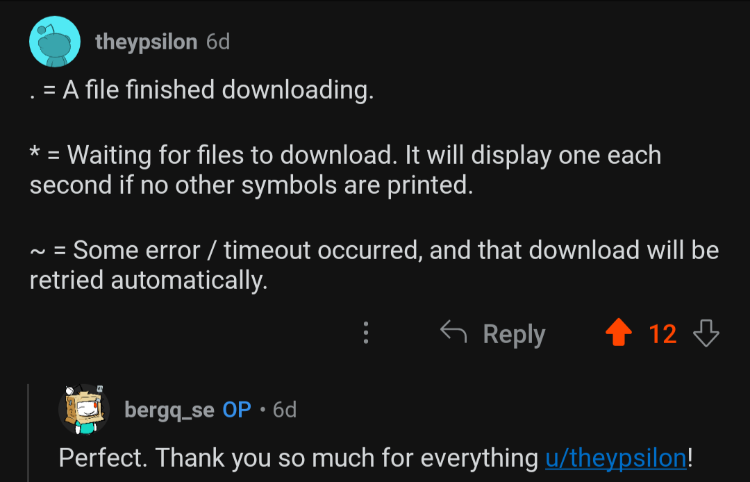
. = A file finished downloading.

\* = Waiting for files to download. It will display one each second if no other symbols are printed.

\~ = Some error / timeout occurred, and that download will be retried automatically.
As described from the maker theypsilon via Reddit:
Playstation MiSTer FPGA core. Is it a good idea to make this core? Yes. Is it a total awesome idea? Absolutely! Is it finished in the time I wrote this? Nope. Yes, now it is!
Conclusion, it is totally worth supporting the developer with a few bucks. “Go find and support FPGAzumSpass via Patreon.” – Mr. Obvious.
—> Install the PSX core via the Update all script.
…or install the PSX core outside of the Update_all script
When you are ready, you can follow the guide at https://vampier.net/PSX/ to install the MiSTer PSX core.
As of 2022-02-02 (unstable build) we can also follow this YouTube clip:
…or in short:
Update the MiSTer
Copy the PSX core to media/fat/_Console/
Make SD card directory /media/fat/games/PSX/
Add/Copy BIOS “SCPH1001.bin” to the new PSX directory. Rename it to “bios.rom”.
Add/Copy bin/cue files to PSX directory.
Add/Copy empty memory card files (mem_v1.mcd, mem_v2.mcd) to somewhere on the MiSTer SD card. I used /media/fat/saves/.
Set controller buttons and mount memory card files in the OSD PSX core. Save settings. Start a game.
4. Bonus
As a celebration to the Sony PlayStation you can look at this massive (1:22:25) history lesson:
Thank you for your time, and good luck if you are about to build something similar yourself!
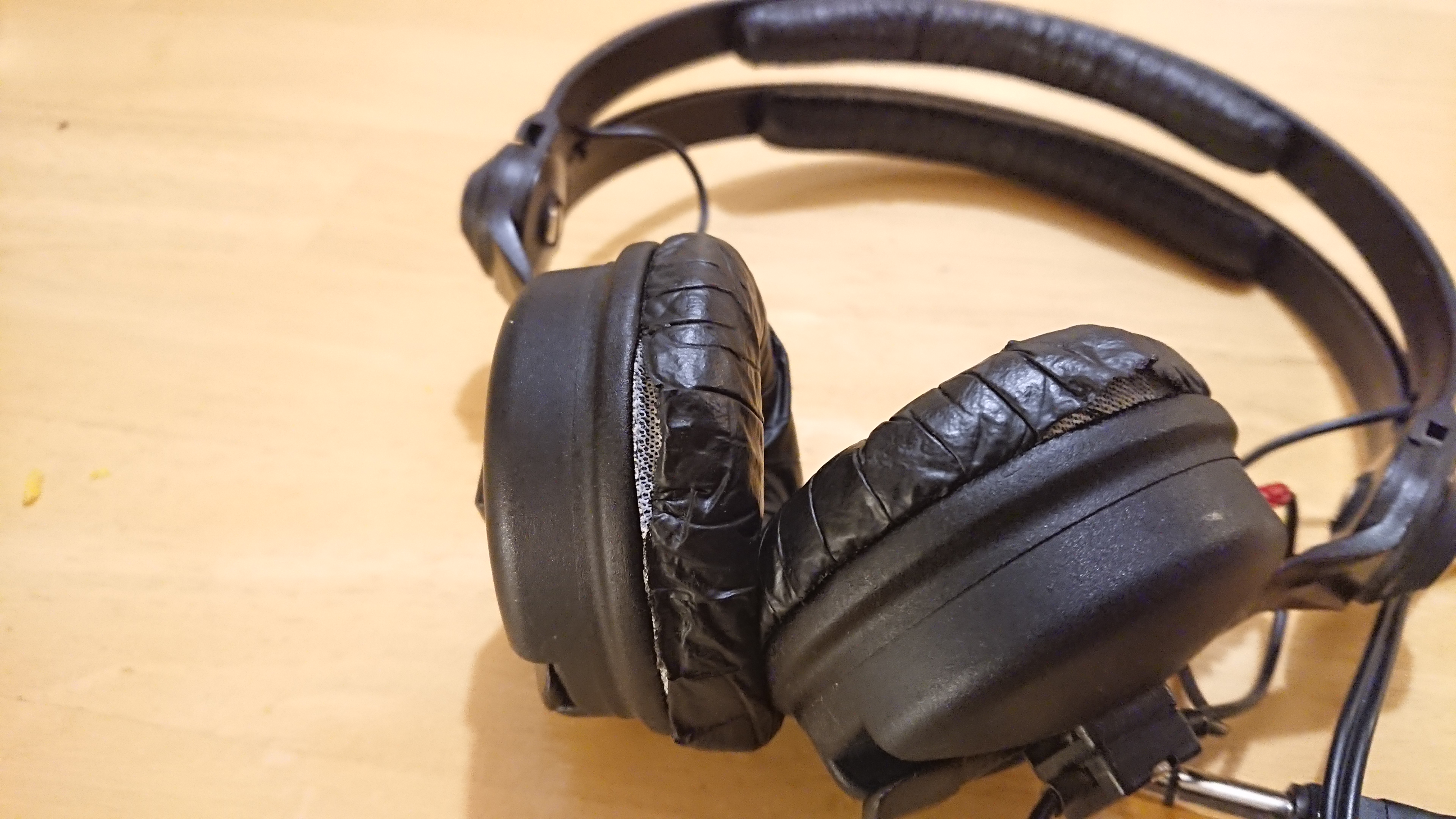
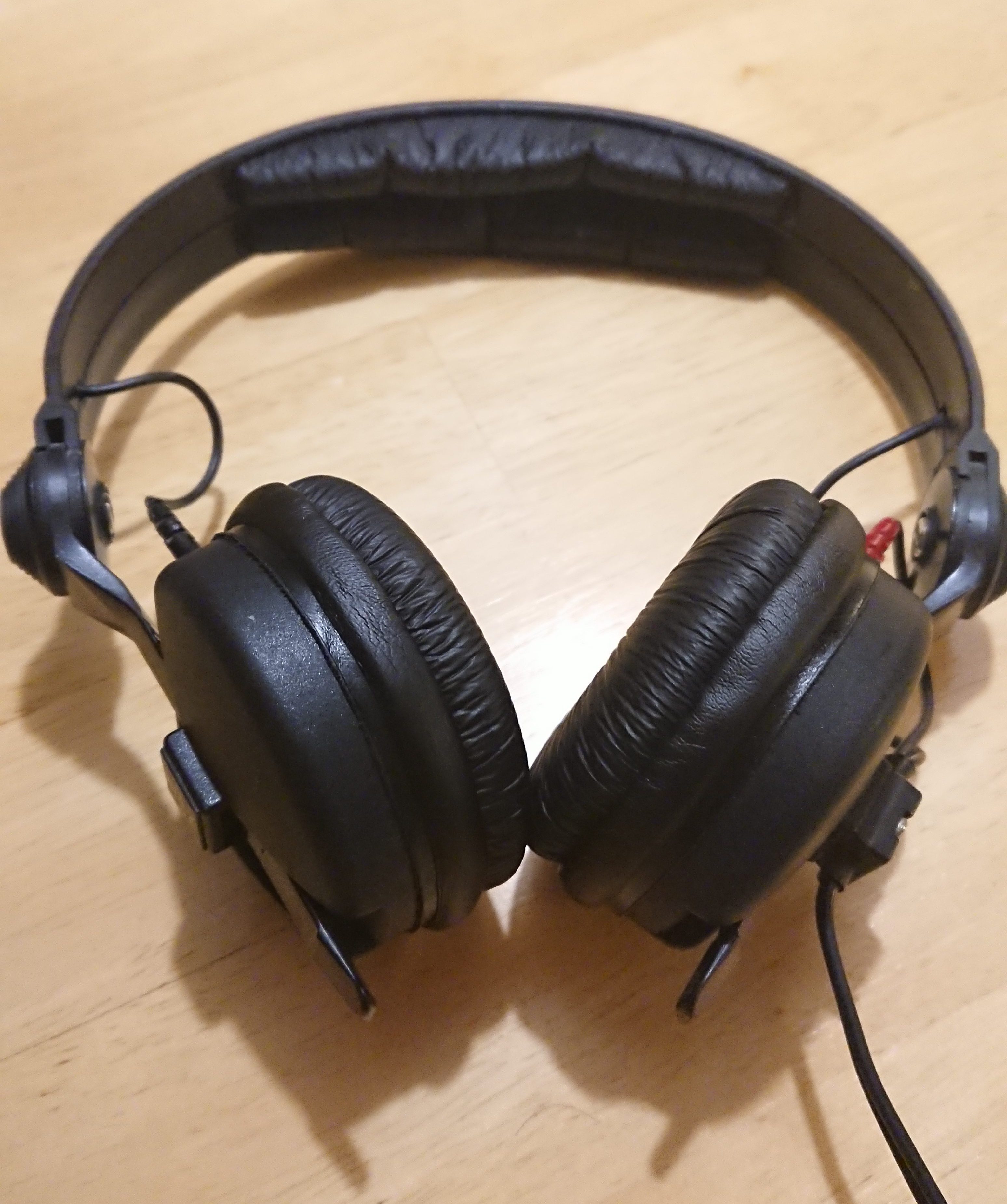
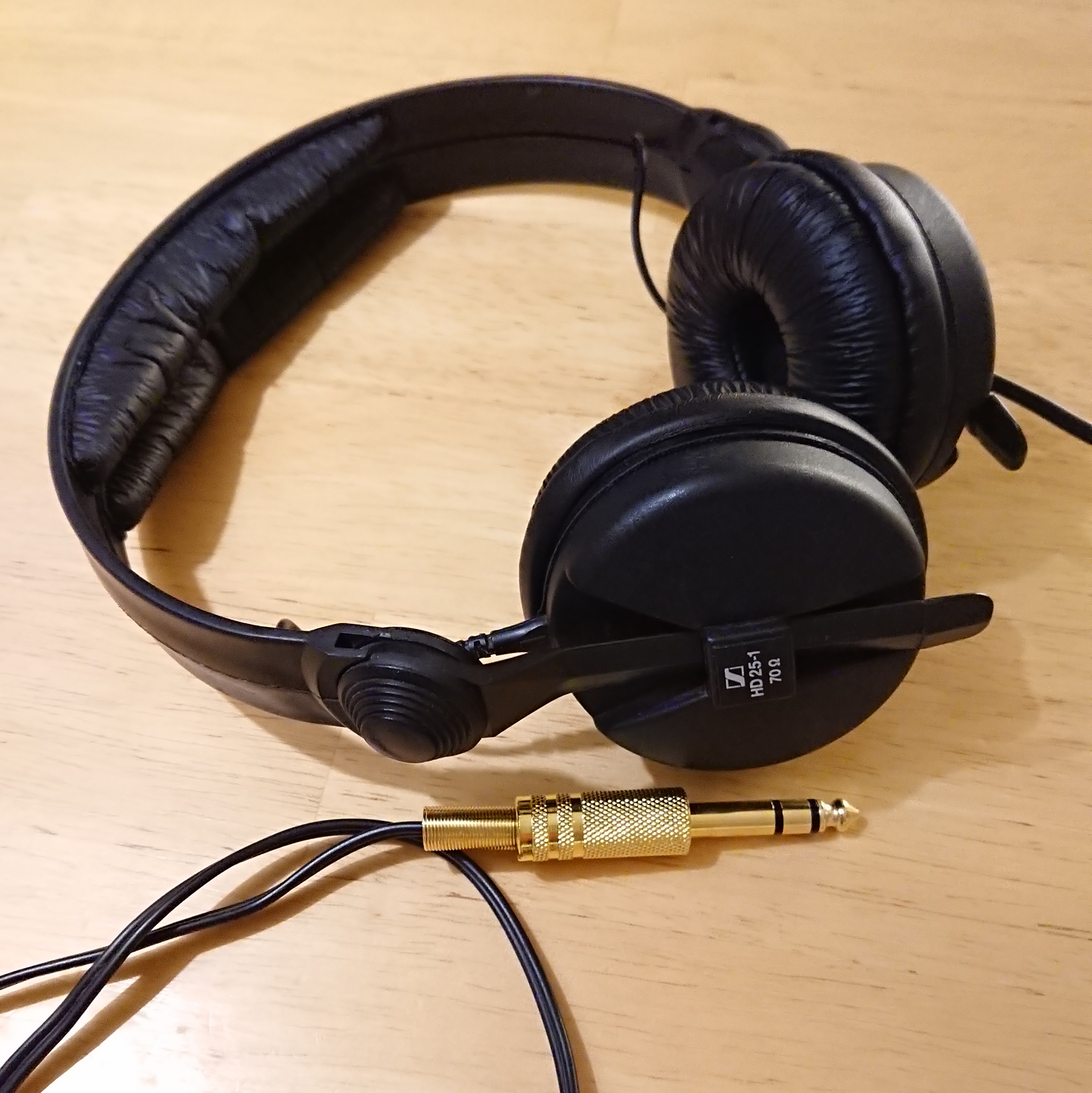
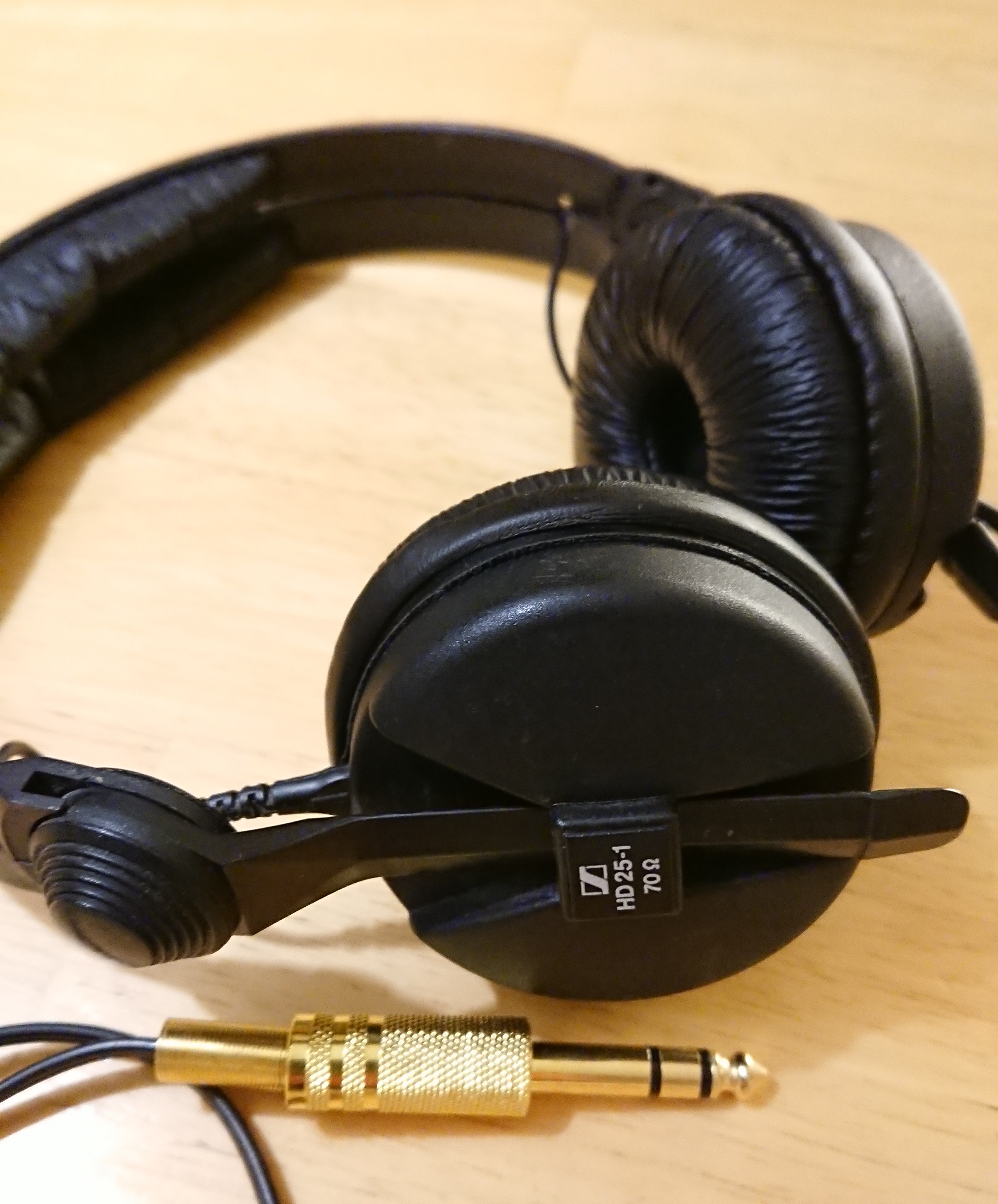
In my (from time to time) series with tech DIY guides (like the Pacemaker SSD upgrade) I will here post you a quick shorten/overview guide of my latest mini project. So here you go Sennheiser HD 25-1 (purchased some what 15 years ago) mini makeover.
I believe this post is for a smaller group of (nerdy) people, so I will write it in English. Enjoy!
Intro – why this restoration is needed:
Glitching/loose headphone contacts.
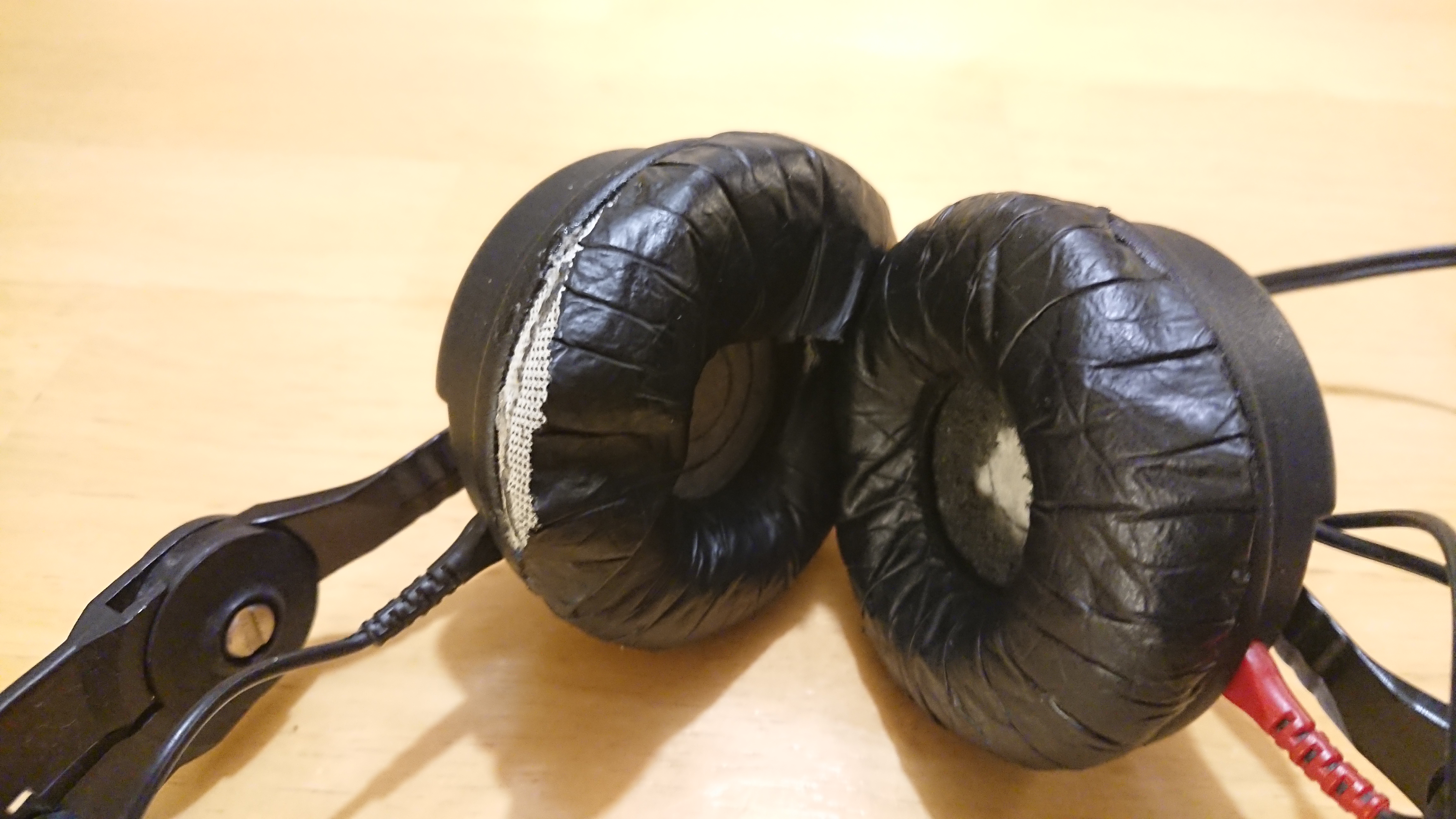
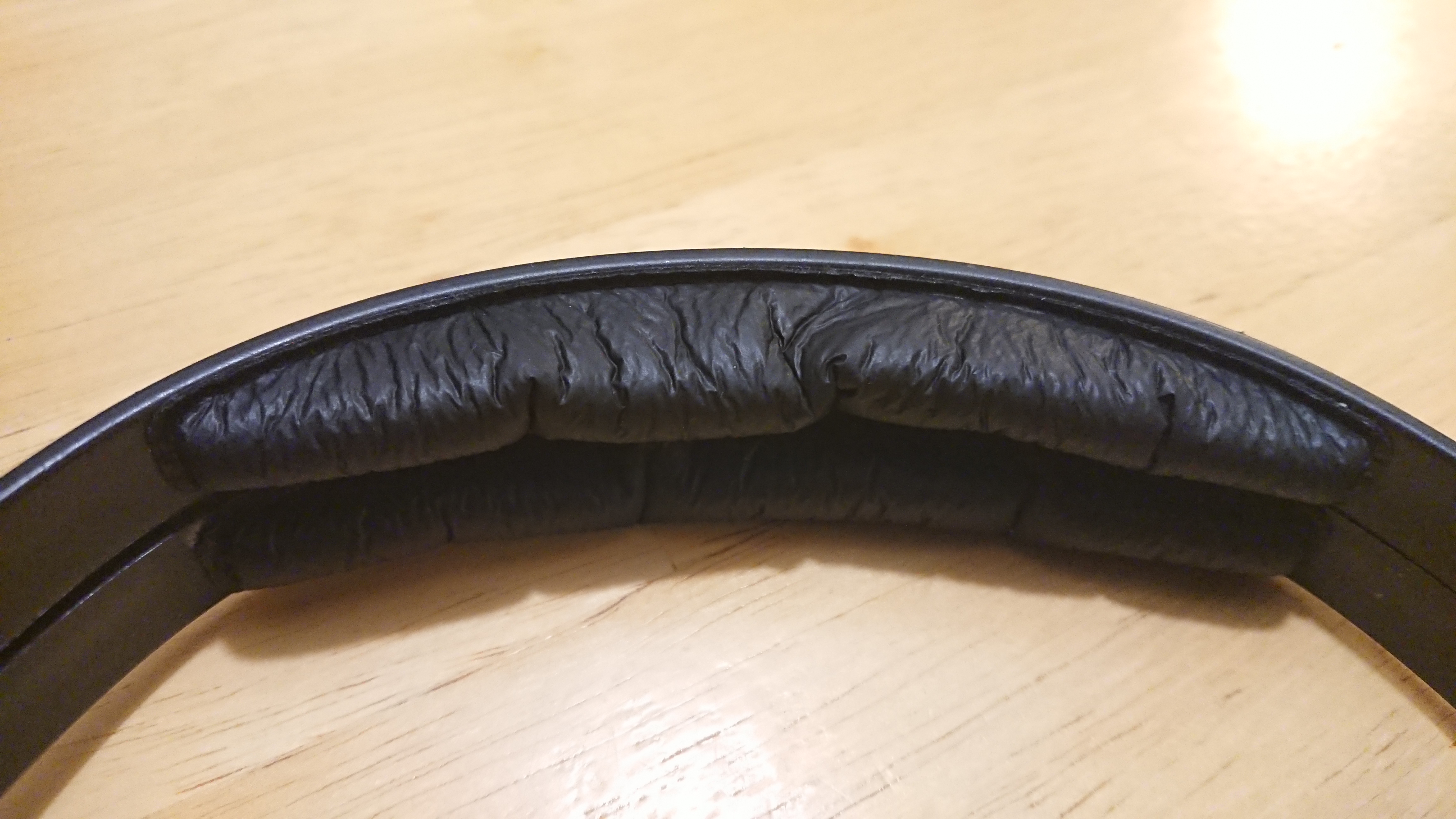
Very old and ragged/torn earpads/headpads
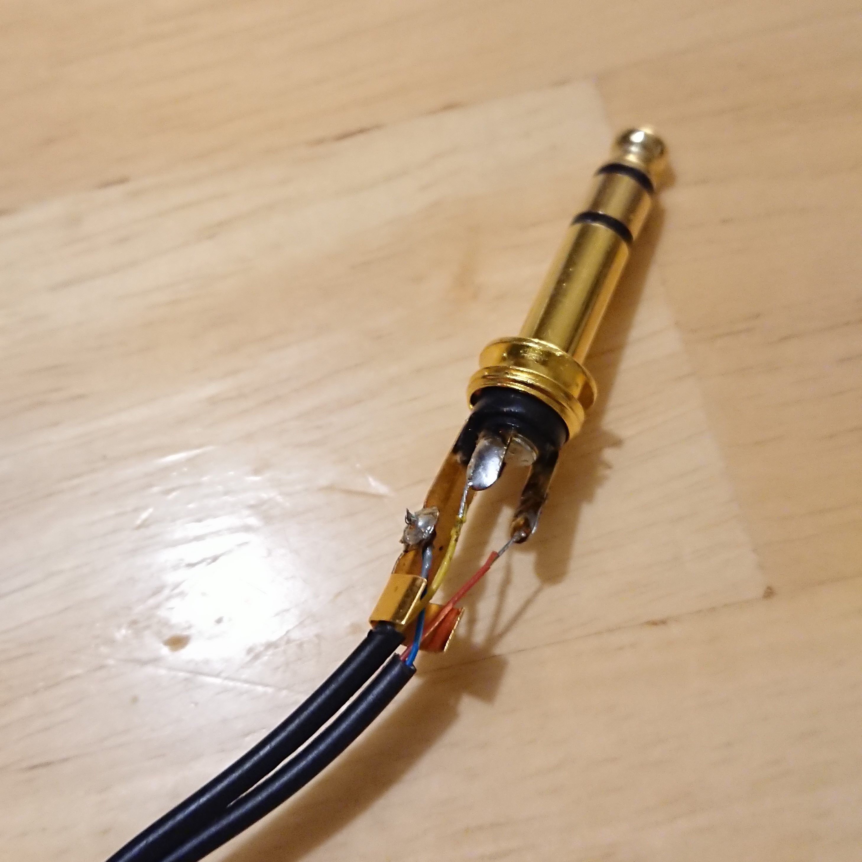
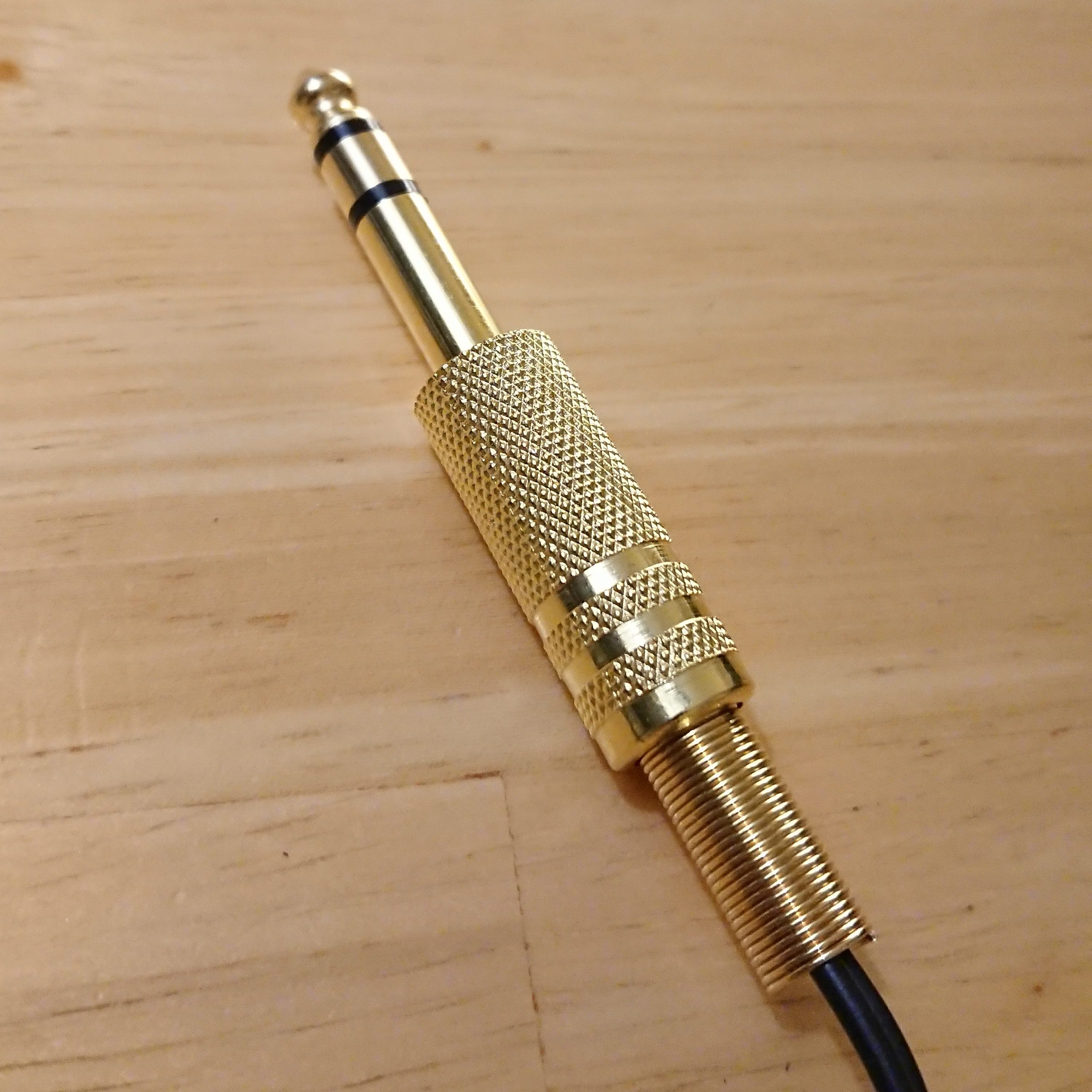
Only 3,5 mm tele plug.
1. Glitching contacts
Unplug the glitching contact (red or black) from the capsule (in my case, it were the red one).
Careful put a thin needle down in the socket and push the small wire/spring a bit to the middle.
Put the contact back in to the socket an test the headphones.
This was old earpads. and yes not even usable at all in my (anyones) opinion.
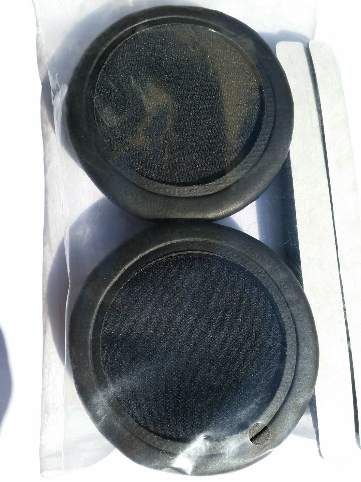
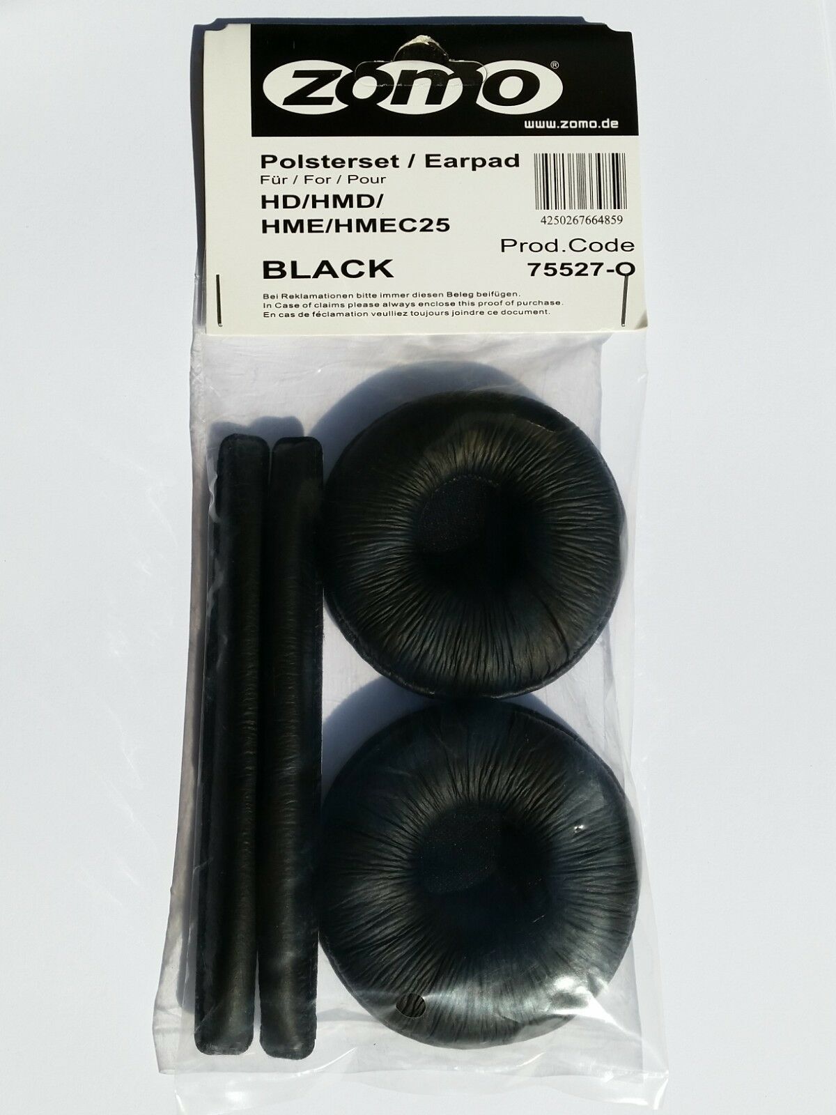
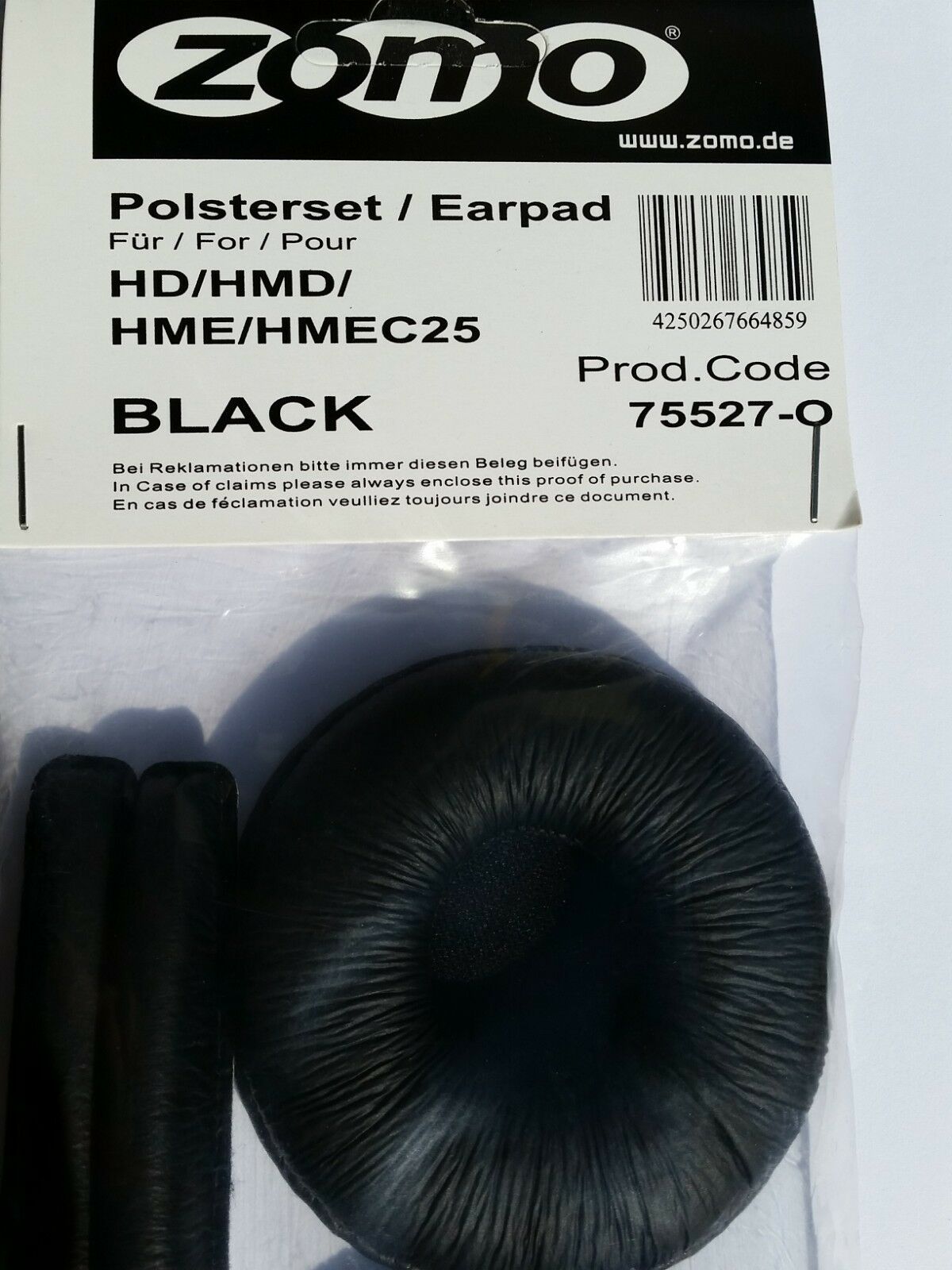
2.2 New ones
If you are struggling with the new earpads to fit your capsules. I unfortunately think you are do it in the correct way. I sat down for a few long minutes and even (carefully) used a fork before I got them in place. Maybe because I bought the non-original from Zomo, but then I got new headpads “for free”.
Finally I got them on the capsules and I am quite pleased with the result. Even if the headpads were a but cheaper looking then the originals. But as I mentioned, I think of them as free goods 😉 Hint: After a while the upper head bands lose the grip, so put some extra strong glue on ut right away.
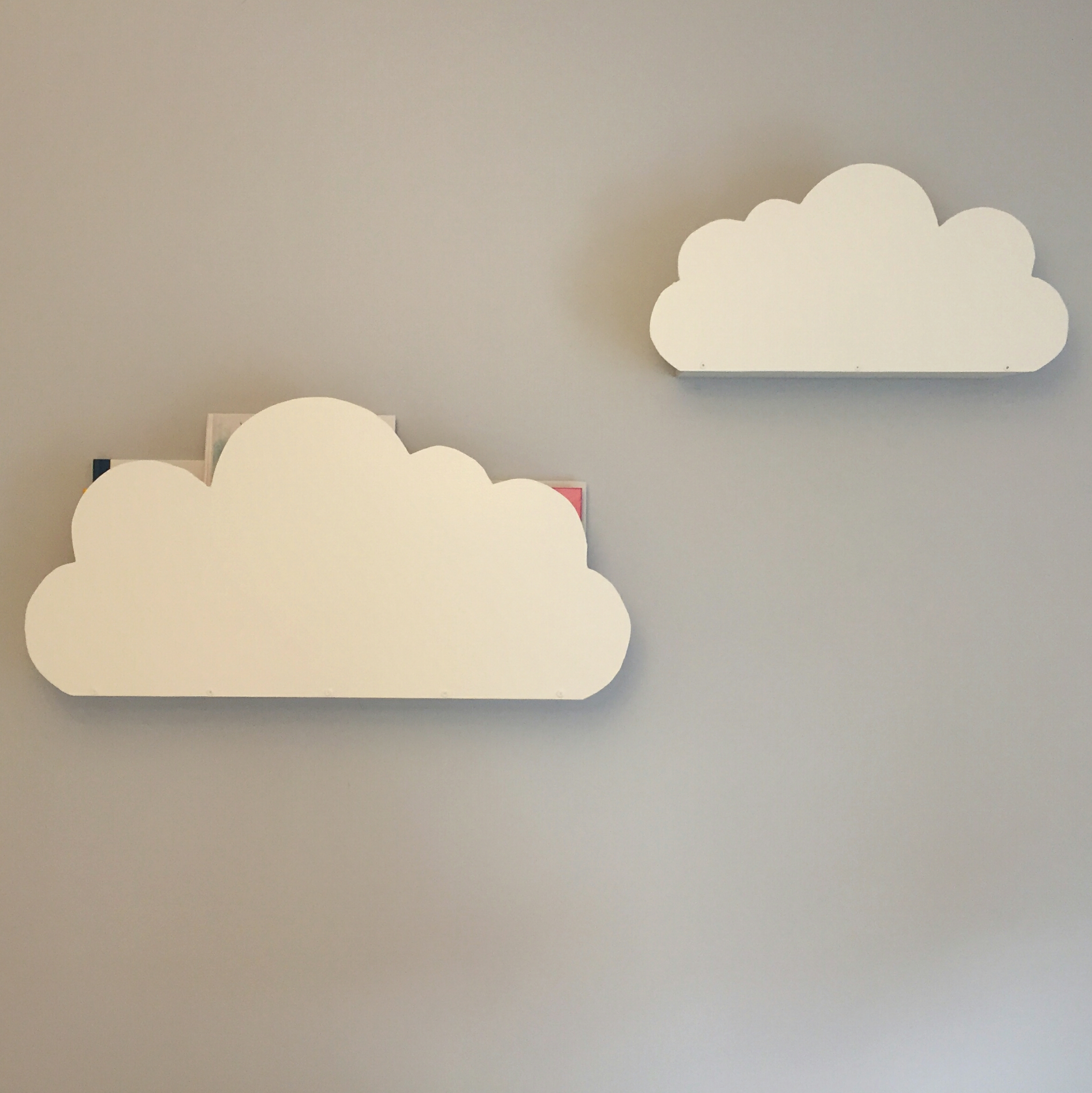
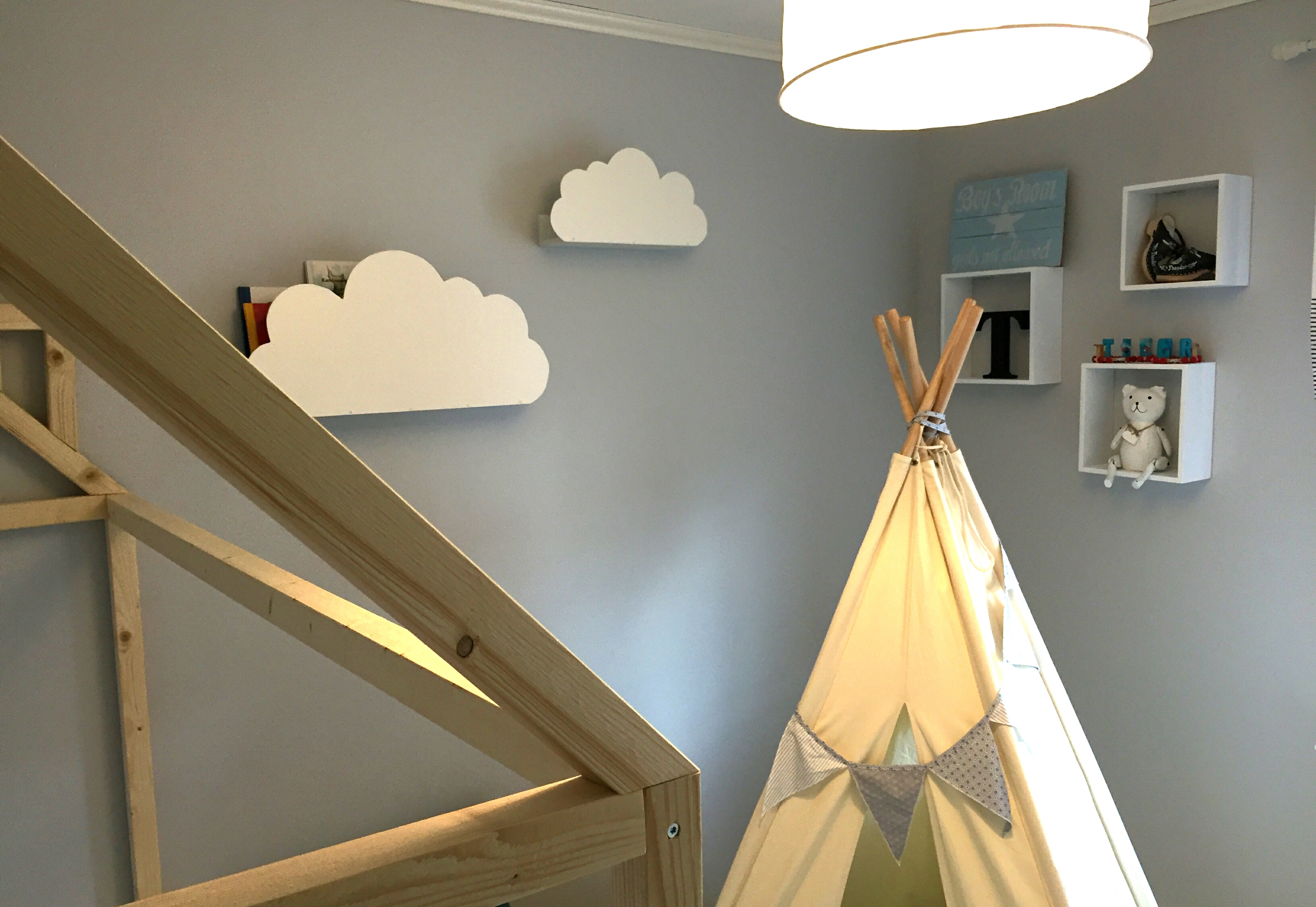
Här tänkte jag presentera en liten “gör-det-själv” -guide (och IKEA-hack) för hur jag gjorde nya hyllor till sonens barnrum. Hyllorna är inspirerade av Trendenser.se och är tänkta att ha vid hans hussäng.
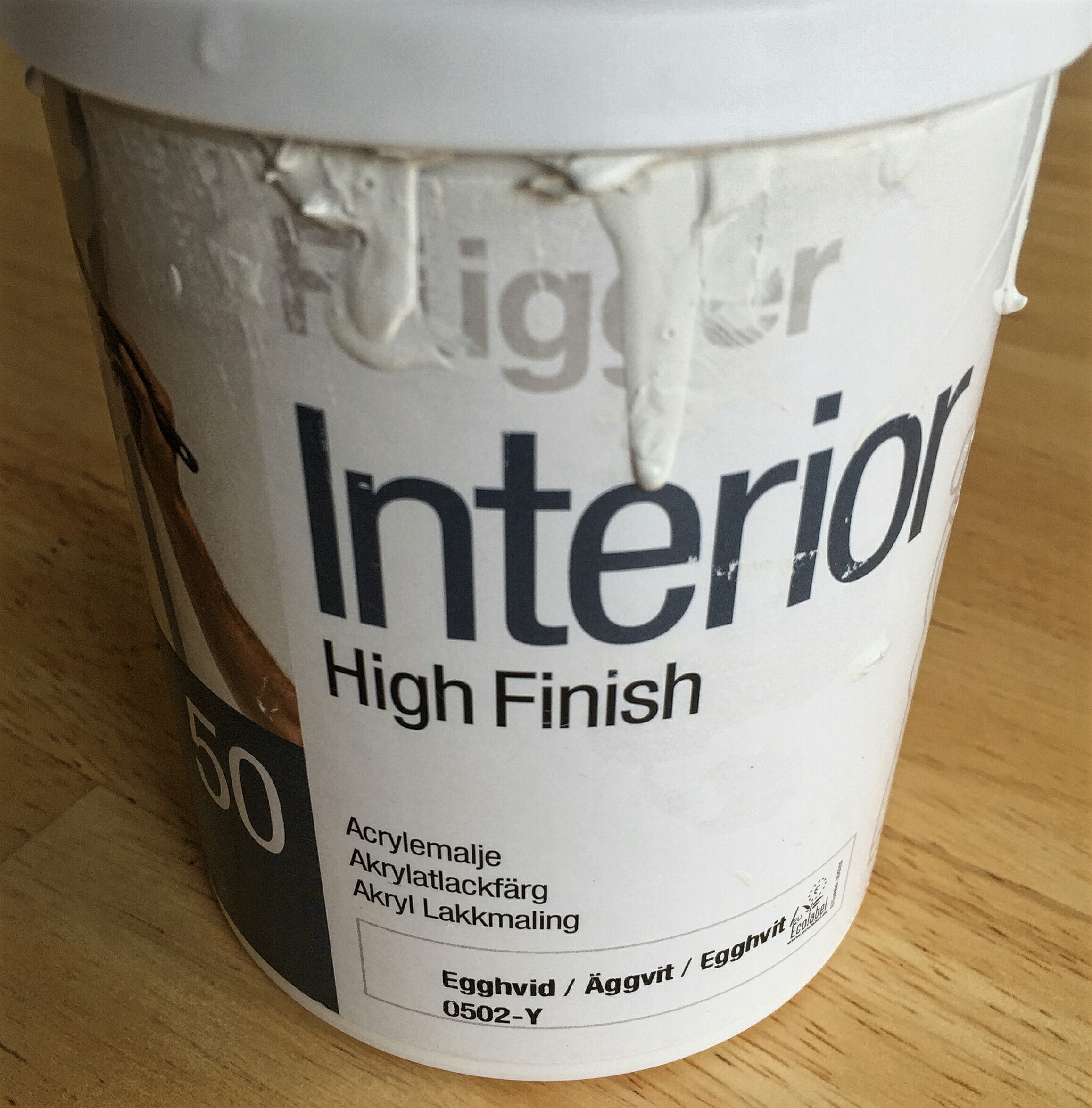
Valfri vit interiörfärg. (Vi målade med Äggvit 0502)
Skruvar 4,5×50 att fästa molnskiva med och förstärkningar. (5×60 i väggen)
3. Såga
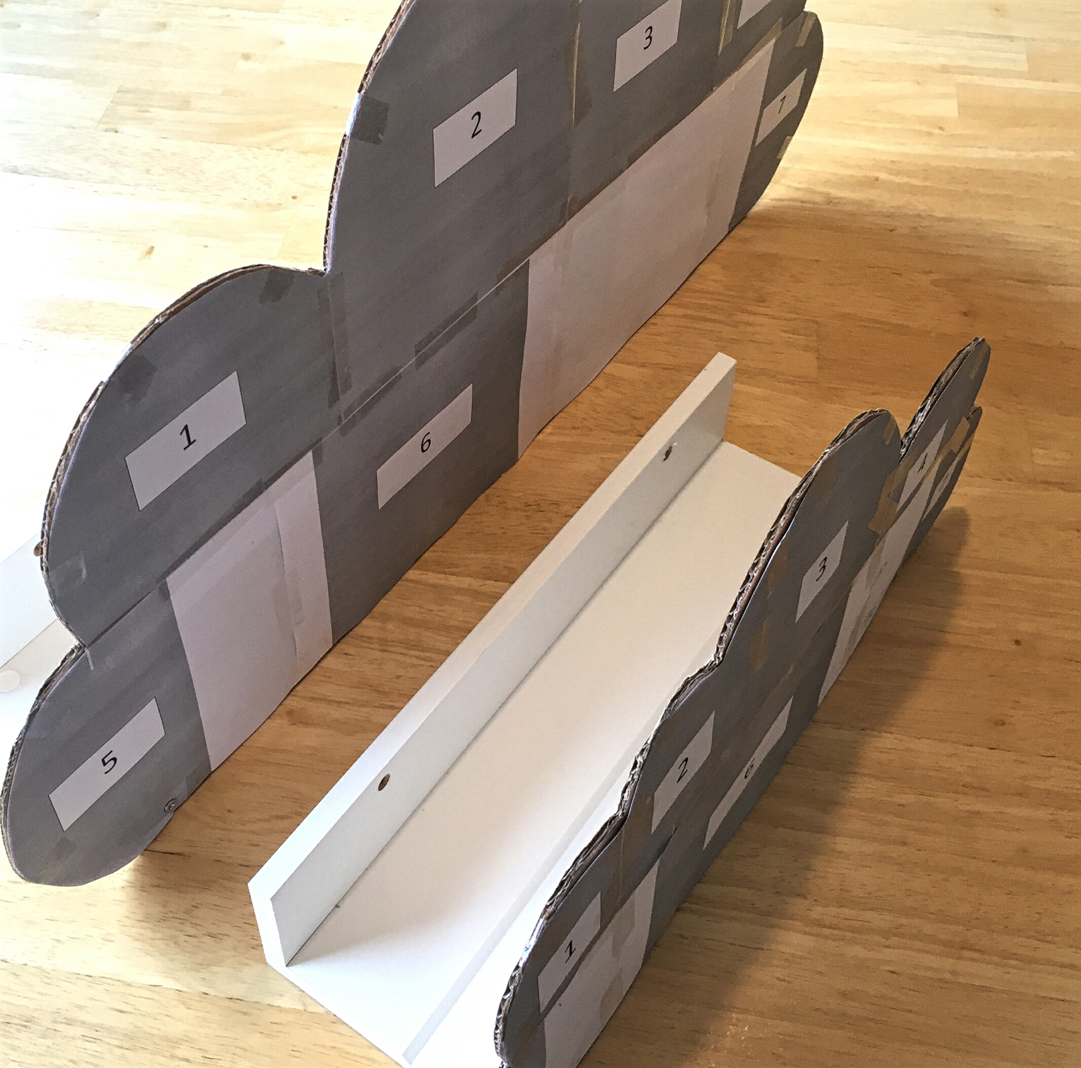
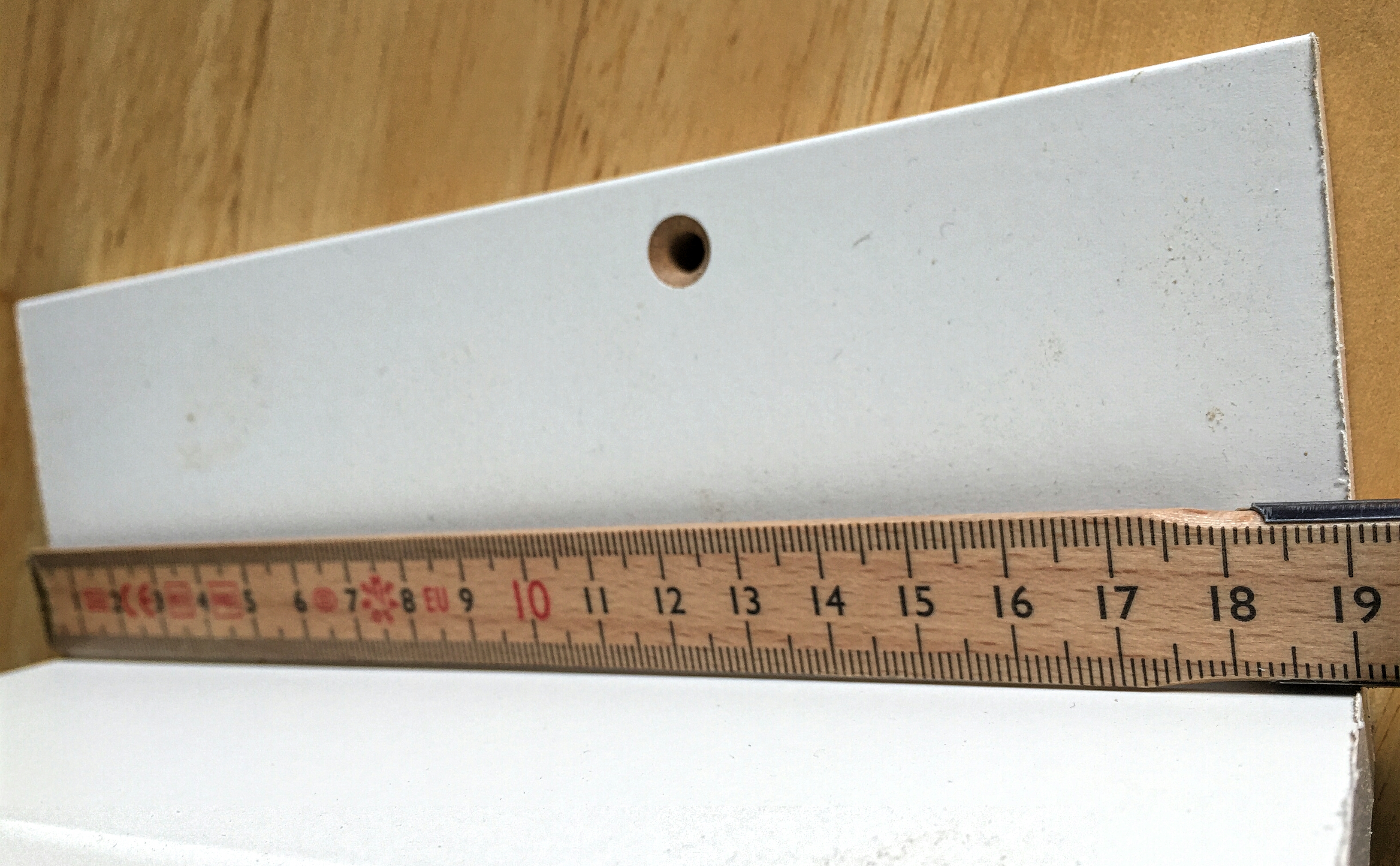
Om “Molnhylla liten” ska göras så behövs en något kortare tavellist (36 cm). Så 19 cm behövs i så fall sågas bort från en list på 55 cm.
Avsågad del av tavellisten. Ett nytt hål (5 mm) behöver, som ni ser, också borras i den kvarvarande delen.
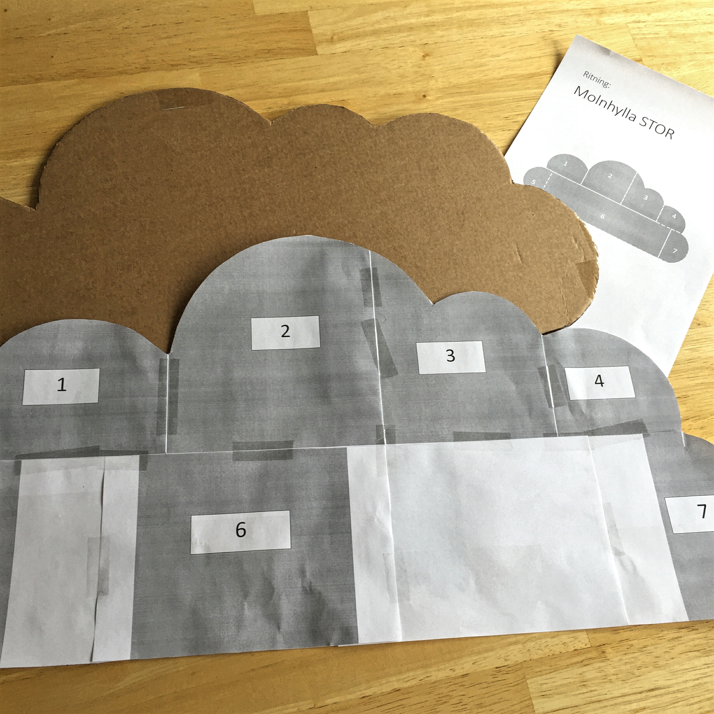
Såga också ut önskad (moln-)form ur hobbyskivorna med en sticksåg.
Sågade skivor.
4. Måla & Montera
Valde att även förstärka hyllplanen med skruvar från baksidan.
Några extra skruvar från baksidan.
Valde också att lägga lite lim mellan molnskivan och tavellisten för att få ytterligare stabilitet.
Målade molnen med vitfärg som vi hade hemma. Är nöjd med resultatet som vi fick när vi använde kulör 0502. Vi målade både fram och baksida, men fungerar givetvis att enbart måla framsidan också.
Färg till molnen – Flügger Interior High Finish Äggvit 0502-Y
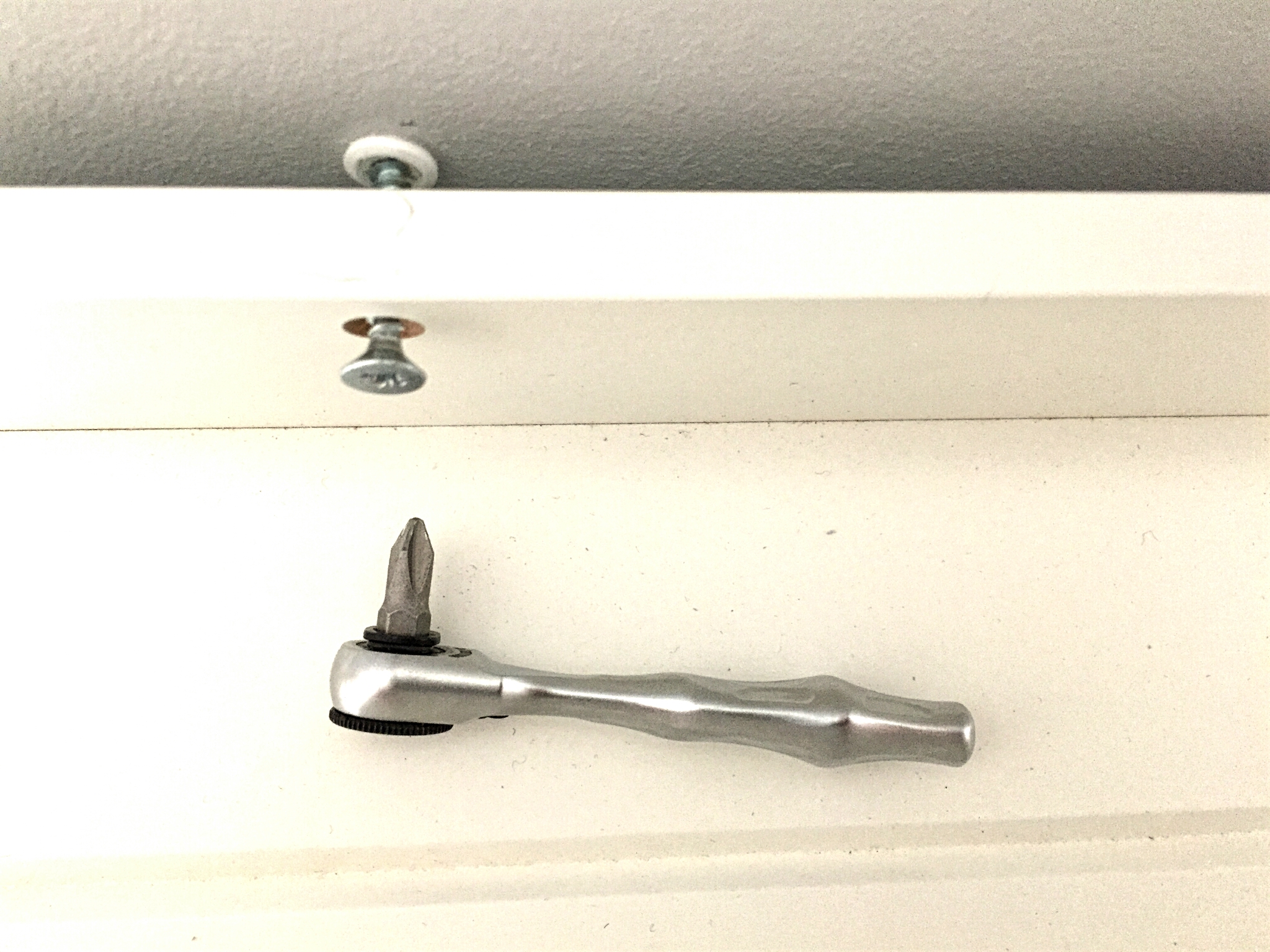
Tänk på att det kan bli något trångt när hyllan ska skruvas fast i väggen om molnskivan är fastskruvad (och limmad).
Verktyg att skruva fast hyllan i väggen med om molnskivan är fastskruvad.
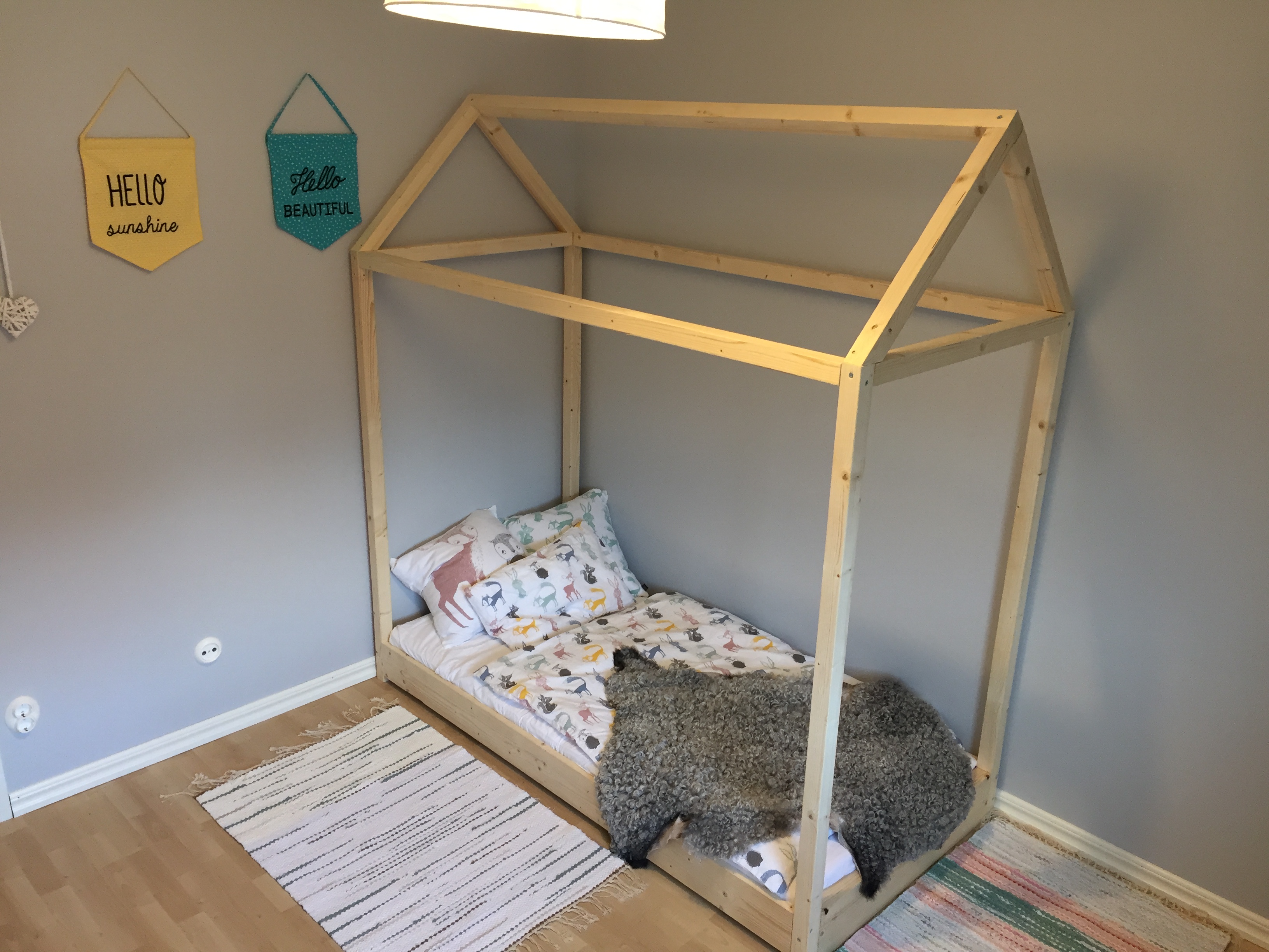
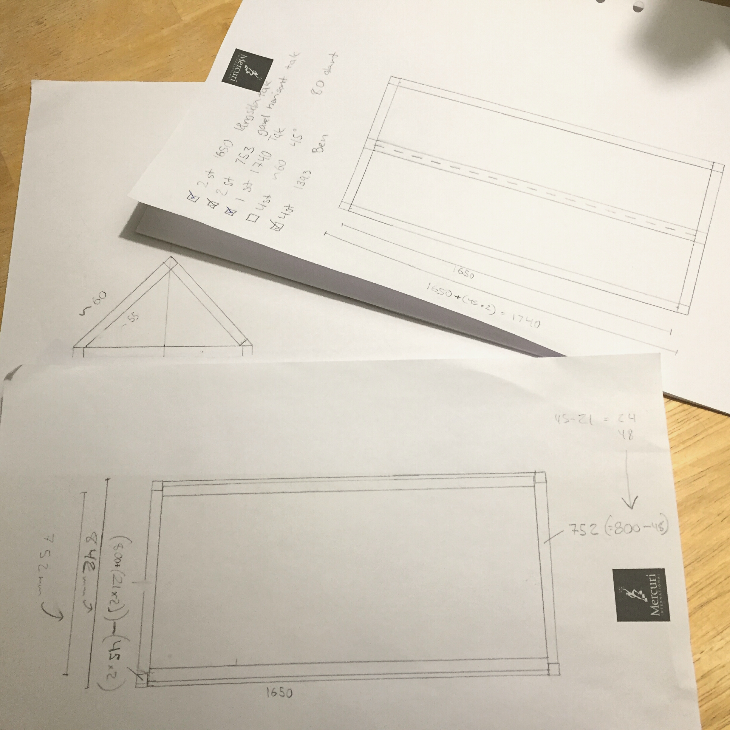
Det som var en tanke att påbörja i tisdags, blev realitet igår (söndag). En liten hussäng står nu alltså klar och användes första gången natten till idag.
Här kommer några bilder som kan användas av andra som vill inspireras och/eller bygga något liknande.
Förberedelser inför husbygget.
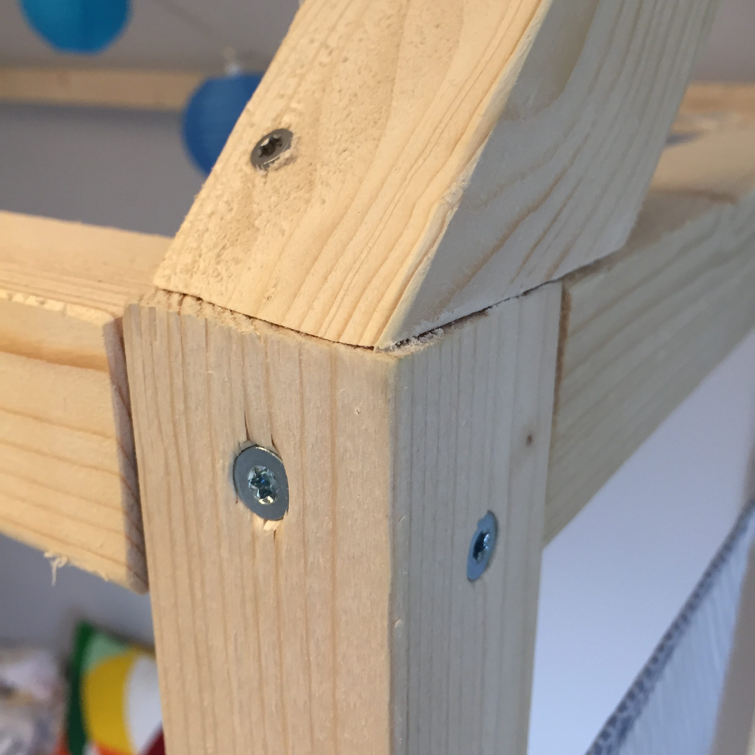
Insida taknock
Här möts tak och knut/ben.
Bild på när tak och knut/ben möts. Taget från insidan.
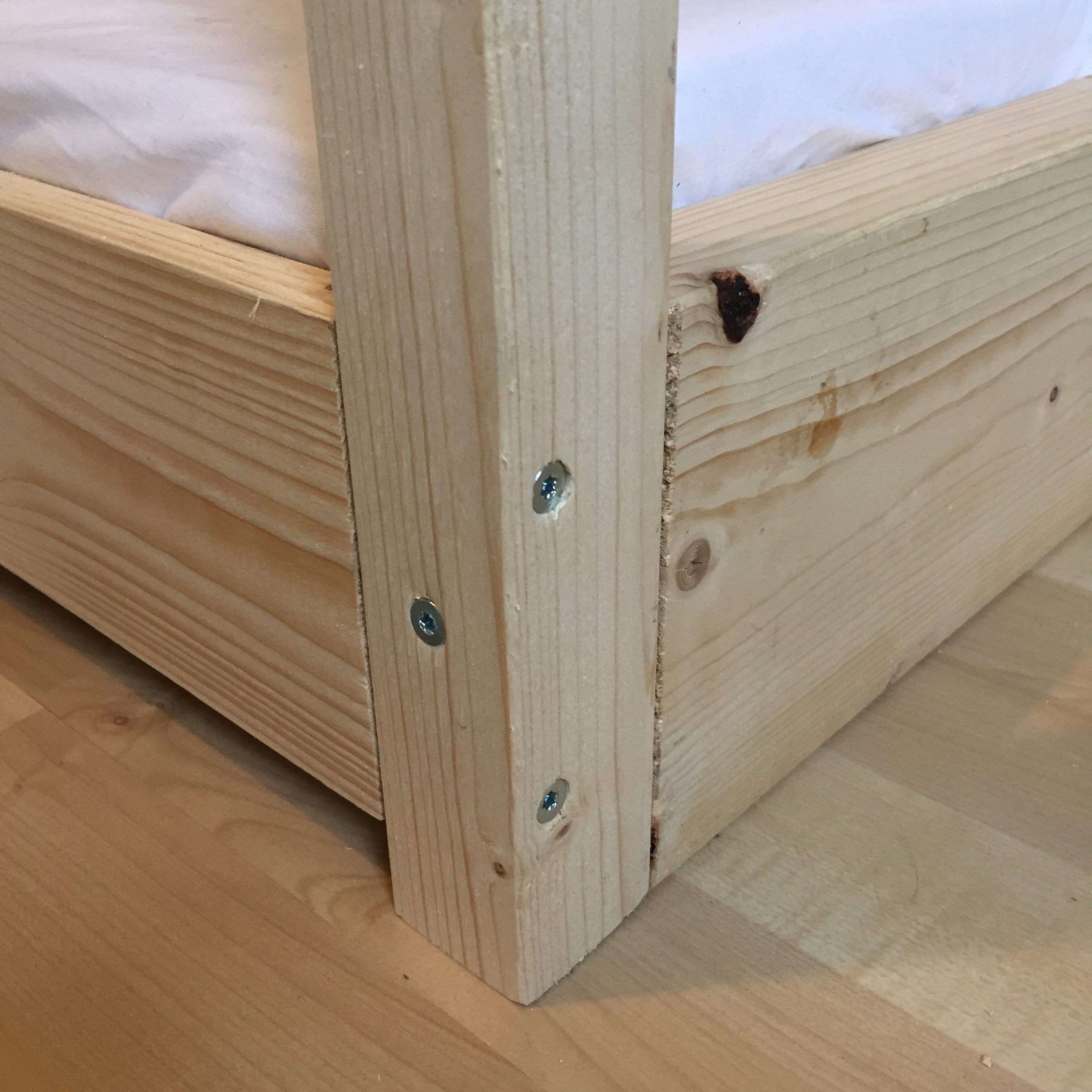
Hörn på sängram nertill. Till vänster syns långsidan med ett mellanrum på 25 mm mellan golv och bräda. Mellanrummet gjordes med tanke på att (1) madrassen skulle få luftflöde så att eventuell funkt inte stannar kvar. Men samtidigt att (2) höjden ska vara så nära golvet att det inte är farligt för en ettåring att trilla ur.